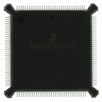
MC68302EH20C Freescale Semiconductor, MC68302EH20C Datasheet - Page 167

MC68302EH20C
Manufacturer Part Number
MC68302EH20C
Description
IC MPU MULTI-PROTOCOL 132-PQFP
Manufacturer
Freescale Semiconductor
Datasheets
1.MC68302AG20C.pdf
(4 pages)
2.MC68302AG20C.pdf
(2 pages)
3.MC68302AG20C.pdf
(13 pages)
4.MC68302EH20C.pdf
(481 pages)
Specifications of MC68302EH20C
Processor Type
M683xx 32-Bit
Speed
20MHz
Voltage
5V
Mounting Type
Surface Mount
Package / Case
132-MQFP, 132-PQFP
Family Name
M68000
Device Core
ColdFire
Device Core Size
32b
Frequency (max)
20MHz
Instruction Set Architecture
RISC
Supply Voltage 1 (typ)
5V
Operating Temp Range
0C to 70C
Operating Temperature Classification
Commercial
Mounting
Surface Mount
Pin Count
132
Package Type
PQFP
Lead Free Status / RoHS Status
Lead free / RoHS Compliant
Features
-
Lead Free Status / Rohs Status
Compliant
Available stocks
Company
Part Number
Manufacturer
Quantity
Price
Company:
Part Number:
MC68302EH20C
Manufacturer:
Freescale Semiconductor
Quantity:
10 000
Part Number:
MC68302EH20C
Manufacturer:
FREESCALE
Quantity:
20 000
Company:
Part Number:
MC68302EH20CB1
Manufacturer:
Freescale Semiconductor
Quantity:
10 000
Company:
Part Number:
MC68302EH20CR2
Manufacturer:
Freescale Semiconductor
Quantity:
10 000
- MC68302AG20C PDF datasheet
- MC68302AG20C PDF datasheet #2
- MC68302AG20C PDF datasheet #3
- MC68302EH20C PDF datasheet #4
- Current page: 167 of 481
- Download datasheet (2Mb)
MAX_IDL
Once a character of data is received on the line, the UART controller begins counting any
idle characters received. If a MAX_IDL number of idle characters is received before the next
data character is received, an idle timeout occurs, and the buffer is closed. This, in turn, can
produce an interrupt request to the M68000 core to receive the data from the buffer.
MAX_IDL then provides a convenient way to demarcate frames in the UART mode (see also
4.5.11.11 UART Error-Handling Procedure.
IDLC
BRKCR
PAREC, FRMEC, NOSEC, BRKEC
UADDR1, UADDR2
MOTOROLA
The UART controller watches the receive line, regardless of whether or not actual data is
being received. If the line is idle, the UART controller counts how many idle characters
have been received. An idle character is defined as 9 to 13 consecutive ones. For a given
application, the number of bits in the idle character is calculated as follows:
This value is used by the RISC to store the current idle counter value in the MAX_IDL tim-
eout process. IDLC is a down counter. It does not need to be initialized or accessed by
the user.
The UART controller will send a break character sequence whenever a STOP TRANSMIT
command is given. The number of break characters sent by the UART controller is deter-
mined by the value in BRKCR. The length of one break character is 9 to 13 zeros depend-
ing on the configuration. The same equation applies for BRKCR as that used for
MAX_IDL. See 4.5.11.8 Send Break for more details. BRKCR is programmed with a value
from 0 (BRKCR = 0) to 65535 (BRKCR = 65535).
These counters are initialized by the user. When the associated condition occurs, they will
be incremented by the RISC controller. See 4.5.11.11 UART Error-Handling Procedure
for more details.
In the multidrop mode, the UART controller can provide automatic address recognition of
two addresses. In this case, the lower order byte of UADDR1 and UADDR2 are pro-
grammed by the user with the two desired addresses. See 4.5.11.6 UART Address Rec-
ognition for more details.
1 + data length (either 7 or 8) + (1 if address bit used) + (1 if parity bit used)
+ number of stop bits (either 1 or 2)
MAX_IDL is programmed with a value from 1 (MAX_IDL = 1) to 65536 (MAX_IDL =
0).
Program MAX_IDL to $0001 for the minimum timeout value; pro-
gram MAX_IDL to $0000 for the maximum timeout value.
MC68302 USER’S MANUAL
NOTE
Communications Processor (CP)
4-47
Related parts for MC68302EH20C
Image
Part Number
Description
Manufacturer
Datasheet
Request
R
Part Number:
Description:
Manufacturer:
Freescale Semiconductor, Inc
Datasheet:

Part Number:
Description:
MC68302 Configuring the Chip Selects on the MC68302
Manufacturer:
Motorola / Freescale Semiconductor

Part Number:
Description:
MC68302 Design Concept - Expanding Interrupts on the MC68302
Manufacturer:
Motorola / Freescale Semiconductor

Part Number:
Description:
MC68302 MC68302 Adapting a WAN Controller to a LAN Environment
Manufacturer:
Motorola / Freescale Semiconductor

Part Number:
Description:
MC68302 EKB Applications - Power Measurements on the MC68302
Manufacturer:
Motorola / Freescale Semiconductor

Part Number:
Description:
MC68302 Interfacing the MC68020 to a Slave MC68302
Manufacturer:
Motorola / Freescale Semiconductor

Part Number:
Description:
MC68302 MC68302 Software Performance
Manufacturer:
Motorola / Freescale Semiconductor

Part Number:
Description:
MC68302 Evaluating EDX on the ADS302
Manufacturer:
Motorola / Freescale Semiconductor

Part Number:
Description:
MC68302 Design Advisory #1 - MC68SC302 Passive ISDN Protocol Engine
Manufacturer:
Motorola / Freescale Semiconductor

Part Number:
Description:
MC68302, MC68360, and MPC860 Characteristics and Design Notes for Crystal Feedback Oscillators
Manufacturer:
Motorola / Freescale Semiconductor
Part Number:
Description:
Mc68302 Integrated Multi-protocol Processor
Manufacturer:
Freescale Semiconductor, Inc
Datasheet:
Part Number:
Description:
Manufacturer:
Freescale Semiconductor, Inc
Datasheet:
Part Number:
Description:
Manufacturer:
Freescale Semiconductor, Inc
Datasheet:
Part Number:
Description:
Manufacturer:
Freescale Semiconductor, Inc
Datasheet:
Part Number:
Description:
Manufacturer:
Freescale Semiconductor, Inc
Datasheet:


