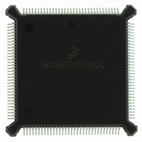
MC68302EH20C Freescale Semiconductor, MC68302EH20C Datasheet - Page 21

MC68302EH20C
Manufacturer Part Number
MC68302EH20C
Description
IC MPU MULTI-PROTOCOL 132-PQFP
Manufacturer
Freescale Semiconductor
Datasheets
1.MC68302AG20C.pdf
(4 pages)
2.MC68302AG20C.pdf
(2 pages)
3.MC68302AG20C.pdf
(13 pages)
4.MC68302EH20C.pdf
(481 pages)
Specifications of MC68302EH20C
Processor Type
M683xx 32-Bit
Speed
20MHz
Voltage
5V
Mounting Type
Surface Mount
Package / Case
132-MQFP, 132-PQFP
Family Name
M68000
Device Core
ColdFire
Device Core Size
32b
Frequency (max)
20MHz
Instruction Set Architecture
RISC
Supply Voltage 1 (typ)
5V
Operating Temp Range
0C to 70C
Operating Temperature Classification
Commercial
Mounting
Surface Mount
Pin Count
132
Package Type
PQFP
Lead Free Status / RoHS Status
Lead free / RoHS Compliant
Features
-
Lead Free Status / Rohs Status
Compliant
Available stocks
Company
Part Number
Manufacturer
Quantity
Price
Company:
Part Number:
MC68302EH20C
Manufacturer:
Freescale Semiconductor
Quantity:
10 000
Part Number:
MC68302EH20C
Manufacturer:
FREESCALE
Quantity:
20 000
Company:
Part Number:
MC68302EH20CB1
Manufacturer:
Freescale Semiconductor
Quantity:
10 000
Company:
Part Number:
MC68302EH20CR2
Manufacturer:
Freescale Semiconductor
Quantity:
10 000
- MC68302AG20C PDF datasheet
- MC68302AG20C PDF datasheet #2
- MC68302AG20C PDF datasheet #3
- MC68302EH20C PDF datasheet #4
- Current page: 21 of 481
- Download datasheet (2Mb)
Table 2-1. M68000 Data Addressing Modes .................................................................2-4
Table 2-2. M68000 Instruction Set Summary.................................................................2-5
Table 2-3. M68000 Instruction Type Variations .............................................................2-6
Table 2-4. M68000 Address Spaces..............................................................................2-7
Table 2-5. M68000 Exception Vector Assignment .........................................................2-8
Table 2-6. System Configuration Register ...................................................................2-14
Table 2-7. System RAM ...............................................................................................2-14
Table 2-8. Parameter RAM ..........................................................................................2-15
Table 2-9. Internal Registers........................................................................................2-17
Table 3-1. SAPR and DAPR Incrementing Rules ........................................................3-10
Table 3-2. IDMA Bus Cycles ........................................................................................3-11
Table 3-3. EXRQ and INRQ Prioritization ....................................................................3-19
Table 3-4. INRQ Prioritization within Interrupt Level 4 .................................................3-19
Table 3-5. Encoding the Interrupt Vector .....................................................................3-23
Table 3-6. Port A Pin Functions ...................................................................................3-31
Table 3-7. Port B Pin Functions ...................................................................................3-32
Table 3-8. DTACK Field Encoding ...............................................................................3-47
Table 3-9. SCR Register Bits .......................................................................................3-51
Table 3-10. Bus Arbitration Priority Table ......................................................................3-58
Table 3-11. DRAM Refresh Memory Map Table............................................................3-68
Table 4-1. The Five Possible SCC Combinations..........................................................4-9
Table 4-2. PCM Highway Mode Pin Functions ............................................................4-17
Table 4-3. PCM Channel Selection..............................................................................4-17
Table 4-4. Typical Bit Rates of Asynchronous Communication ...................................4-27
Table 4-5. Transmit Data Delay (TCLK Periods) .........................................................4-28
Table 4-6. SCC Parameter RAM Memory Map............................................................4-35
Table 4-7. UART Specific Parameter RAM..................................................................4-46
Table 4-8. HDLC-Specific Parameter RAM..................................................................4-69
Table 4-9. BISYNC Specific Parameter RAM ..............................................................4-86
Table 4-10. DDCMP Specific Parameter RAM ............................................................4-104
Table 4-11. Transparent-Specific Parameter RAM ......................................................4-125
MOTOROLA
Table
Number
Communications Processor (CP)
System Integration Block (SIB)
LIST OF TABLES
MC68000/MC68008 Core
MC68302 USER’S MANUAL
Section 2
Section 3
Section 4
Title
Number
Page
xxi
Related parts for MC68302EH20C
Image
Part Number
Description
Manufacturer
Datasheet
Request
R
Part Number:
Description:
Manufacturer:
Freescale Semiconductor, Inc
Datasheet:

Part Number:
Description:
MC68302 Configuring the Chip Selects on the MC68302
Manufacturer:
Motorola / Freescale Semiconductor

Part Number:
Description:
MC68302 Design Concept - Expanding Interrupts on the MC68302
Manufacturer:
Motorola / Freescale Semiconductor

Part Number:
Description:
MC68302 MC68302 Adapting a WAN Controller to a LAN Environment
Manufacturer:
Motorola / Freescale Semiconductor

Part Number:
Description:
MC68302 EKB Applications - Power Measurements on the MC68302
Manufacturer:
Motorola / Freescale Semiconductor

Part Number:
Description:
MC68302 Interfacing the MC68020 to a Slave MC68302
Manufacturer:
Motorola / Freescale Semiconductor

Part Number:
Description:
MC68302 MC68302 Software Performance
Manufacturer:
Motorola / Freescale Semiconductor

Part Number:
Description:
MC68302 Evaluating EDX on the ADS302
Manufacturer:
Motorola / Freescale Semiconductor

Part Number:
Description:
MC68302 Design Advisory #1 - MC68SC302 Passive ISDN Protocol Engine
Manufacturer:
Motorola / Freescale Semiconductor

Part Number:
Description:
MC68302, MC68360, and MPC860 Characteristics and Design Notes for Crystal Feedback Oscillators
Manufacturer:
Motorola / Freescale Semiconductor
Part Number:
Description:
Mc68302 Integrated Multi-protocol Processor
Manufacturer:
Freescale Semiconductor, Inc
Datasheet:
Part Number:
Description:
Manufacturer:
Freescale Semiconductor, Inc
Datasheet:
Part Number:
Description:
Manufacturer:
Freescale Semiconductor, Inc
Datasheet:
Part Number:
Description:
Manufacturer:
Freescale Semiconductor, Inc
Datasheet:
Part Number:
Description:
Manufacturer:
Freescale Semiconductor, Inc
Datasheet:


