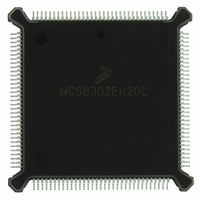
MC68302EH20C Freescale Semiconductor, MC68302EH20C Datasheet - Page 191

MC68302EH20C
Manufacturer Part Number
MC68302EH20C
Description
IC MPU MULTI-PROTOCOL 132-PQFP
Manufacturer
Freescale Semiconductor
Datasheets
1.MC68302AG20C.pdf
(4 pages)
2.MC68302AG20C.pdf
(2 pages)
3.MC68302AG20C.pdf
(13 pages)
4.MC68302EH20C.pdf
(481 pages)
Specifications of MC68302EH20C
Processor Type
M683xx 32-Bit
Speed
20MHz
Voltage
5V
Mounting Type
Surface Mount
Package / Case
132-MQFP, 132-PQFP
Family Name
M68000
Device Core
ColdFire
Device Core Size
32b
Frequency (max)
20MHz
Instruction Set Architecture
RISC
Supply Voltage 1 (typ)
5V
Operating Temp Range
0C to 70C
Operating Temperature Classification
Commercial
Mounting
Surface Mount
Pin Count
132
Package Type
PQFP
Lead Free Status / RoHS Status
Lead free / RoHS Compliant
Features
-
Lead Free Status / Rohs Status
Compliant
Available stocks
Company
Part Number
Manufacturer
Quantity
Price
Company:
Part Number:
MC68302EH20C
Manufacturer:
Freescale Semiconductor
Quantity:
10 000
Part Number:
MC68302EH20C
Manufacturer:
FREESCALE
Quantity:
20 000
Company:
Part Number:
MC68302EH20CB1
Manufacturer:
Freescale Semiconductor
Quantity:
10 000
Company:
Part Number:
MC68302EH20CR2
Manufacturer:
Freescale Semiconductor
Quantity:
10 000
- MC68302AG20C PDF datasheet
- MC68302AG20C PDF datasheet #2
- MC68302AG20C PDF datasheet #3
- MC68302EH20C PDF datasheet #4
- Current page: 191 of 481
- Download datasheet (2Mb)
ENTER HUNT MODE Command
4.5.12.6 HDLC Address Recognition
Each HDLC controller has five 16-bit registers for address recognition: one mask register
and four address registers (HMASK, HADDR1, HADDR2, HADDR3, and HADDR4). The
HDLC controller reads the frame's address from the HDLC receiver, checks it against the
four address register values, and then masks the result with the user-defined HMASK. A one
in HMASK represents a bit position for which address comparison should occur; a zero rep-
resents a masked bit position. Upon an address match, the address and the data following
are written into the data buffers. When the addresses are not matched and the frame is error
free, the nonmatching address received counter (NMARC) is incremented.
Examples of 16- and 8-bit HDLC address recognition are shown in Figure 4-25.
4.5.12.7 HDLC Maximum Frame Length Register (MFLR)
The HDLC controller checks the length of an incoming HDLC frame against the user-defined
value given in this 16-bit register. If this limit is exceeded, the remainder of the incoming
HDLC frame is discarded, and the LG (Rx frame too long) bit is set in the last BD belonging
to that frame. The HDLC controller waits to the end of the frame and reports the frame status
MOTOROLA
After a hardware or software reset and the enabling of the channel by its SCC mode reg-
ister, the channel is in the receive enable mode and will use the first BD in the table.
The ENTER HUNT MODE command is generally used to force the HDLC receiver to abort
reception of the current frame, generate an RXB interrupt (if enabled) as the buffer is
closed, and enter the hunt mode. In the hunt mode, the HDLC controller continually scans
the input data stream for the flag sequence. After receiving the command, the current re-
ceive buffer is closed, and the CRC is reset. Further frame reception will use the next BD.
If an enabled receiver has been disabled by clearing ENR in the SCC mode register), the
ENTER HUNT MODE command must be given to the channel before setting ENR again.
Subsequent frames will then be received, starting with the next BD.
FLAG
$7E
RECOGNIZES ONE 16-BIT ADDRESS (HADDR1) AND
ADDRESS
THE 16-BIT BROADCAST ADDRESS (HADDR2).
HADDR1
HADDR2
HADDR3
HADDR4
For 8-bit addresses, mask out the eight high-order bits in the
HMASK register.
HMASK
$68
16-BIT ADDRESS RECOGNITION
Figure 4-25. HDLC Address Recognition Examples
ADDRESS
$AA
$FFFF
$AA68
$AA68
$AA68
$FFFF
CONTROL
MC68302 USER’S MANUAL
$44
NOTE
ETC.
FLAG
$7E
RECOGNIZES A SINGLE 8-BIT ADDRESS (HADDR1).
HADDR2
HADDR3
HADDR4
HADDR1
HMASK
Communications Processor (CP)
8-BIT ADDRESS RECOGNITION
ADDRESS
$55
$XX55
$XX55
$XX55
$XX55
$00FF
CONTROL
$44
ETC.
4-71
Related parts for MC68302EH20C
Image
Part Number
Description
Manufacturer
Datasheet
Request
R
Part Number:
Description:
Manufacturer:
Freescale Semiconductor, Inc
Datasheet:

Part Number:
Description:
MC68302 Configuring the Chip Selects on the MC68302
Manufacturer:
Motorola / Freescale Semiconductor

Part Number:
Description:
MC68302 Design Concept - Expanding Interrupts on the MC68302
Manufacturer:
Motorola / Freescale Semiconductor

Part Number:
Description:
MC68302 MC68302 Adapting a WAN Controller to a LAN Environment
Manufacturer:
Motorola / Freescale Semiconductor

Part Number:
Description:
MC68302 EKB Applications - Power Measurements on the MC68302
Manufacturer:
Motorola / Freescale Semiconductor

Part Number:
Description:
MC68302 Interfacing the MC68020 to a Slave MC68302
Manufacturer:
Motorola / Freescale Semiconductor

Part Number:
Description:
MC68302 MC68302 Software Performance
Manufacturer:
Motorola / Freescale Semiconductor

Part Number:
Description:
MC68302 Evaluating EDX on the ADS302
Manufacturer:
Motorola / Freescale Semiconductor

Part Number:
Description:
MC68302 Design Advisory #1 - MC68SC302 Passive ISDN Protocol Engine
Manufacturer:
Motorola / Freescale Semiconductor

Part Number:
Description:
MC68302, MC68360, and MPC860 Characteristics and Design Notes for Crystal Feedback Oscillators
Manufacturer:
Motorola / Freescale Semiconductor
Part Number:
Description:
Mc68302 Integrated Multi-protocol Processor
Manufacturer:
Freescale Semiconductor, Inc
Datasheet:
Part Number:
Description:
Manufacturer:
Freescale Semiconductor, Inc
Datasheet:
Part Number:
Description:
Manufacturer:
Freescale Semiconductor, Inc
Datasheet:
Part Number:
Description:
Manufacturer:
Freescale Semiconductor, Inc
Datasheet:
Part Number:
Description:
Manufacturer:
Freescale Semiconductor, Inc
Datasheet:


