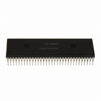
HD6473258P10 Renesas Electronics America, HD6473258P10 Datasheet - Page 78

HD6473258P10
Manufacturer Part Number
HD6473258P10
Description
IC H8 MCU OTP 32K 64DIP
Manufacturer
Renesas Electronics America
Series
H8® H8/325r
Datasheet
1.HD6413238F10.pdf
(301 pages)
Specifications of HD6473258P10
Core Processor
H8/300
Core Size
8-Bit
Speed
10MHz
Connectivity
SCI, UART/USART
Number Of I /o
53
Program Memory Size
32KB (32K x 8)
Program Memory Type
OTP
Ram Size
1K x 8
Voltage - Supply (vcc/vdd)
4.5 V ~ 5.5 V
Oscillator Type
External
Operating Temperature
-20°C ~ 75°C
Package / Case
64-DIP
Lead Free Status / RoHS Status
Contains lead / RoHS non-compliant
Eeprom Size
-
Data Converters
-
Peripherals
-
Available stocks
Company
Part Number
Manufacturer
Quantity
Price
Company:
Part Number:
HD6473258P10
Manufacturer:
EXEL
Quantity:
6 218
Company:
Part Number:
HD6473258P10V
Manufacturer:
RENESAS
Quantity:
600
Part Number:
HD6473258P10V
Manufacturer:
HITACHI/日立
Quantity:
20 000
- Current page: 78 of 301
- Download datasheet (2Mb)
4.3.4 Internal Interrupts
Seventeen internal interrupts can be requested by the on-chip supporting modules. All of them are
masked when the I bit in the CCR is set. In addition, they can all be enabled or disabled by bits in
the control registers of the on-chip supporting modules. When one of these interrupts is accepted,
the I bit is set to 1 to mask further interrupts (except NMI).
Power can be conserved by waiting for an internal interrupt in sleep mode, in which the CPU halts
but the on-chip supporting modules continue to run. When the interrupt arrives, the CPU returns to
the program-execution state, services the interrupt, then resumes execution of the main program.
See section 12, Power-Down State for further information on the sleep mode.
The input strobe interrupt (ISI) can also be waited for in software standby mode. The chip recovers
from software standby mode when an input strobe interrupt is requested.
The internal interrupt signals received by the interrupt controller are generated from flag bits in the
registers of the on-chip supporting modules. The interrupt controller does not reset these flag bits
when accepting the interrupt.
For the vector numbers and priority order of these interrupts, see table 4-2.
Note: When disabling internal interrupts, note the following points.
1. Set the interrupt mask (I) to 1 before disabling an internal interrupt or clearing its interrupt flag.
2. If an instruction that disables or clears an internal interrupt is executed while the interrupt mask
Example: A sample program for disabling the output compare A interrupt is shown below. The
OCIAE bit in the TCR should be cleared only when I = 1, as in this example.
ORC
BCLR
ANDC
(I) is cleared to 0, and the interrupt is requested during execution of the instruction, the CPU
resolves this conflict as follows:
If one or more other interrupts are also requested, the other interrupt with the highest priority
is served.
If no other interrupt is requested, the CPU branches to the reset address.
#80, CCR
#5, @TCR
#7F, CCR
; Set I bit
; Disable output compare A interrupt
; Clear I bit
69
Related parts for HD6473258P10
Image
Part Number
Description
Manufacturer
Datasheet
Request
R

Part Number:
Description:
KIT STARTER FOR M16C/29
Manufacturer:
Renesas Electronics America
Datasheet:

Part Number:
Description:
KIT STARTER FOR R8C/2D
Manufacturer:
Renesas Electronics America
Datasheet:

Part Number:
Description:
R0K33062P STARTER KIT
Manufacturer:
Renesas Electronics America
Datasheet:

Part Number:
Description:
KIT STARTER FOR R8C/23 E8A
Manufacturer:
Renesas Electronics America
Datasheet:

Part Number:
Description:
KIT STARTER FOR R8C/25
Manufacturer:
Renesas Electronics America
Datasheet:

Part Number:
Description:
KIT STARTER H8S2456 SHARPE DSPLY
Manufacturer:
Renesas Electronics America
Datasheet:

Part Number:
Description:
KIT STARTER FOR R8C38C
Manufacturer:
Renesas Electronics America
Datasheet:

Part Number:
Description:
KIT STARTER FOR R8C35C
Manufacturer:
Renesas Electronics America
Datasheet:

Part Number:
Description:
KIT STARTER FOR R8CL3AC+LCD APPS
Manufacturer:
Renesas Electronics America
Datasheet:

Part Number:
Description:
KIT STARTER FOR RX610
Manufacturer:
Renesas Electronics America
Datasheet:

Part Number:
Description:
KIT STARTER FOR R32C/118
Manufacturer:
Renesas Electronics America
Datasheet:

Part Number:
Description:
KIT DEV RSK-R8C/26-29
Manufacturer:
Renesas Electronics America
Datasheet:

Part Number:
Description:
KIT STARTER FOR SH7124
Manufacturer:
Renesas Electronics America
Datasheet:

Part Number:
Description:
KIT STARTER FOR H8SX/1622
Manufacturer:
Renesas Electronics America
Datasheet:

Part Number:
Description:
KIT DEV FOR SH7203
Manufacturer:
Renesas Electronics America
Datasheet:


