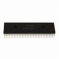
HD6473258P10 Renesas Electronics America, HD6473258P10 Datasheet - Page 22

HD6473258P10
Manufacturer Part Number
HD6473258P10
Description
IC H8 MCU OTP 32K 64DIP
Manufacturer
Renesas Electronics America
Series
H8® H8/325r
Datasheet
1.HD6413238F10.pdf
(301 pages)
Specifications of HD6473258P10
Core Processor
H8/300
Core Size
8-Bit
Speed
10MHz
Connectivity
SCI, UART/USART
Number Of I /o
53
Program Memory Size
32KB (32K x 8)
Program Memory Type
OTP
Ram Size
1K x 8
Voltage - Supply (vcc/vdd)
4.5 V ~ 5.5 V
Oscillator Type
External
Operating Temperature
-20°C ~ 75°C
Package / Case
64-DIP
Lead Free Status / RoHS Status
Contains lead / RoHS non-compliant
Eeprom Size
-
Data Converters
-
Peripherals
-
Available stocks
Company
Part Number
Manufacturer
Quantity
Price
Company:
Part Number:
HD6473258P10
Manufacturer:
EXEL
Quantity:
6 218
Company:
Part Number:
HD6473258P10V
Manufacturer:
RENESAS
Quantity:
600
Part Number:
HD6473258P10V
Manufacturer:
HITACHI/日立
Quantity:
20 000
- Current page: 22 of 301
- Download datasheet (2Mb)
(2) Pin Functions: Table 1-3 gives a concise description of the function of each pin.
Table 1-3. Pin Functions (1)
Type
Power
Clock
System
control
Address
bus
Data bus
Bus
control
Symbol
V
V
XTAL
EXTAL
Ø
E
RES
STBY
A
D
WAIT
RD
WR
AS
CC
SS
15
7
to D
to A
0
0
I/O
I
I
I
I
O
O
I
I
O
I/O
I
O
O
O
Name and function
Power: Connected to the power supply (+5 V or +3 V). Connect
both V
Ground: Connected to ground (0 V). Connect both V
system power supply (0 V).
Crystal: Connected to a crystal oscillator. The crystal frequency
must be double the desired system clock frequency. If an external
clock is input at the EXTAL pin, a reverse-phase clock should be
input at the XTAL pin.
External crystal: Connected to a crystal oscillator or external
clock. The frequency of the external clock must be double the
desired system clock frequency. See section 14, Clock Pulse
Generator for examples of connections to a crystal and external
clock.
System clock: Supplies the system clock to peripheral devices.
Enable clock: Supplies an E clock to peripheral devices.
Reset: A low input causes the chip to reset.
Standby: A transition to the hardware standby mode
(a power-down state) occurs when a low input is received at the
STBY pin.
Address bus: Address output pins.
Data bus: 8-Bit bidirectional data bus.
Wait: Requests the CPU to insert T
when an off-chip address is accessed.
Read: Goes low to indicate that the CPU is reading an external
address.
Write: Goes low to indicate that the CPU is writing to an external
address.
Address Strobe: Goes low to indicate that there is a valid address
on the address bus.
CC
pins to the system power supply (+5 V or +3 V).
12
W
states into the bus cycle
SS
pins to the
Related parts for HD6473258P10
Image
Part Number
Description
Manufacturer
Datasheet
Request
R

Part Number:
Description:
KIT STARTER FOR M16C/29
Manufacturer:
Renesas Electronics America
Datasheet:

Part Number:
Description:
KIT STARTER FOR R8C/2D
Manufacturer:
Renesas Electronics America
Datasheet:

Part Number:
Description:
R0K33062P STARTER KIT
Manufacturer:
Renesas Electronics America
Datasheet:

Part Number:
Description:
KIT STARTER FOR R8C/23 E8A
Manufacturer:
Renesas Electronics America
Datasheet:

Part Number:
Description:
KIT STARTER FOR R8C/25
Manufacturer:
Renesas Electronics America
Datasheet:

Part Number:
Description:
KIT STARTER H8S2456 SHARPE DSPLY
Manufacturer:
Renesas Electronics America
Datasheet:

Part Number:
Description:
KIT STARTER FOR R8C38C
Manufacturer:
Renesas Electronics America
Datasheet:

Part Number:
Description:
KIT STARTER FOR R8C35C
Manufacturer:
Renesas Electronics America
Datasheet:

Part Number:
Description:
KIT STARTER FOR R8CL3AC+LCD APPS
Manufacturer:
Renesas Electronics America
Datasheet:

Part Number:
Description:
KIT STARTER FOR RX610
Manufacturer:
Renesas Electronics America
Datasheet:

Part Number:
Description:
KIT STARTER FOR R32C/118
Manufacturer:
Renesas Electronics America
Datasheet:

Part Number:
Description:
KIT DEV RSK-R8C/26-29
Manufacturer:
Renesas Electronics America
Datasheet:

Part Number:
Description:
KIT STARTER FOR SH7124
Manufacturer:
Renesas Electronics America
Datasheet:

Part Number:
Description:
KIT STARTER FOR H8SX/1622
Manufacturer:
Renesas Electronics America
Datasheet:

Part Number:
Description:
KIT DEV FOR SH7203
Manufacturer:
Renesas Electronics America
Datasheet:


