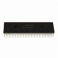
HD6473258P10 Renesas Electronics America, HD6473258P10 Datasheet - Page 135

HD6473258P10
Manufacturer Part Number
HD6473258P10
Description
IC H8 MCU OTP 32K 64DIP
Manufacturer
Renesas Electronics America
Series
H8® H8/325r
Datasheet
1.HD6413238F10.pdf
(301 pages)
Specifications of HD6473258P10
Core Processor
H8/300
Core Size
8-Bit
Speed
10MHz
Connectivity
SCI, UART/USART
Number Of I /o
53
Program Memory Size
32KB (32K x 8)
Program Memory Type
OTP
Ram Size
1K x 8
Voltage - Supply (vcc/vdd)
4.5 V ~ 5.5 V
Oscillator Type
External
Operating Temperature
-20°C ~ 75°C
Package / Case
64-DIP
Lead Free Status / RoHS Status
Contains lead / RoHS non-compliant
Eeprom Size
-
Data Converters
-
Peripherals
-
Available stocks
Company
Part Number
Manufacturer
Quantity
Price
Company:
Part Number:
HD6473258P10
Manufacturer:
EXEL
Quantity:
6 218
Company:
Part Number:
HD6473258P10V
Manufacturer:
RENESAS
Quantity:
600
Part Number:
HD6473258P10V
Manufacturer:
HITACHI/日立
Quantity:
20 000
- Current page: 135 of 301
- Download datasheet (2Mb)
In addition, if the output enable bit (OEA or OEB) in the timer output compare control register
(TCR) is set to 1, when the output compare register and FRC values match, the logic level selected
by the output level bit (OLVLA or OLVLB) in the TCSR is output at the output compare pin
(FTOA or FTOB).
Because OCRA and OCRB are 16-bit registers, a temporary register (TEMP) is used for write
access, as explained in section 7.3, CPU Interface.
OCRA and OCRB are initialized to H’FFFF at a reset and in the standby modes.
7.2.3 Input Capture Register (ICR) – H’FF98
Bit
Initial 0
value
Read/ R
Write
The input capture register is a 16-bit read-only register.
When the rising or falling edge of the signal at the input capture pin (FTI) is detected, the current
value of the FRC is copied to the input capture register (ICR). At the same time, the input capture
flag (ICF) in the timer control/status register (TCSR) is set to 1. The input capture edge is selected
by the input edge select bit (IEDG) in the TCSR.
Because the input capture register is a 16-bit register, a temporary register (TEMP) is used when it
is read. See Section 7.3, CPU Interface for details.
To ensure input capture, when the noise canceler is not used, the width of the input capture pulse
(FTI) should be at least 1.5 system clock cycles (1.5·Ø).
15
14
R
0
13
R
0
12
R
0
11
R
0
10
R
0
R
9
0
127
R
8
0
R
7
0
R
6
0
R
5
0
R
4
0
R
3
0
R
2
0
R
1
0
R
0
0
Related parts for HD6473258P10
Image
Part Number
Description
Manufacturer
Datasheet
Request
R

Part Number:
Description:
KIT STARTER FOR M16C/29
Manufacturer:
Renesas Electronics America
Datasheet:

Part Number:
Description:
KIT STARTER FOR R8C/2D
Manufacturer:
Renesas Electronics America
Datasheet:

Part Number:
Description:
R0K33062P STARTER KIT
Manufacturer:
Renesas Electronics America
Datasheet:

Part Number:
Description:
KIT STARTER FOR R8C/23 E8A
Manufacturer:
Renesas Electronics America
Datasheet:

Part Number:
Description:
KIT STARTER FOR R8C/25
Manufacturer:
Renesas Electronics America
Datasheet:

Part Number:
Description:
KIT STARTER H8S2456 SHARPE DSPLY
Manufacturer:
Renesas Electronics America
Datasheet:

Part Number:
Description:
KIT STARTER FOR R8C38C
Manufacturer:
Renesas Electronics America
Datasheet:

Part Number:
Description:
KIT STARTER FOR R8C35C
Manufacturer:
Renesas Electronics America
Datasheet:

Part Number:
Description:
KIT STARTER FOR R8CL3AC+LCD APPS
Manufacturer:
Renesas Electronics America
Datasheet:

Part Number:
Description:
KIT STARTER FOR RX610
Manufacturer:
Renesas Electronics America
Datasheet:

Part Number:
Description:
KIT STARTER FOR R32C/118
Manufacturer:
Renesas Electronics America
Datasheet:

Part Number:
Description:
KIT DEV RSK-R8C/26-29
Manufacturer:
Renesas Electronics America
Datasheet:

Part Number:
Description:
KIT STARTER FOR SH7124
Manufacturer:
Renesas Electronics America
Datasheet:

Part Number:
Description:
KIT STARTER FOR H8SX/1622
Manufacturer:
Renesas Electronics America
Datasheet:

Part Number:
Description:
KIT DEV FOR SH7203
Manufacturer:
Renesas Electronics America
Datasheet:


