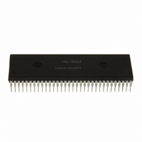
HD6473258P10 Renesas Electronics America, HD6473258P10 Datasheet - Page 38

HD6473258P10
Manufacturer Part Number
HD6473258P10
Description
IC H8 MCU OTP 32K 64DIP
Manufacturer
Renesas Electronics America
Series
H8® H8/325r
Datasheet
1.HD6413238F10.pdf
(301 pages)
Specifications of HD6473258P10
Core Processor
H8/300
Core Size
8-Bit
Speed
10MHz
Connectivity
SCI, UART/USART
Number Of I /o
53
Program Memory Size
32KB (32K x 8)
Program Memory Type
OTP
Ram Size
1K x 8
Voltage - Supply (vcc/vdd)
4.5 V ~ 5.5 V
Oscillator Type
External
Operating Temperature
-20°C ~ 75°C
Package / Case
64-DIP
Lead Free Status / RoHS Status
Contains lead / RoHS non-compliant
Eeprom Size
-
Data Converters
-
Peripherals
-
Available stocks
Company
Part Number
Manufacturer
Quantity
Price
Company:
Part Number:
HD6473258P10
Manufacturer:
EXEL
Quantity:
6 218
Company:
Part Number:
HD6473258P10V
Manufacturer:
RENESAS
Quantity:
600
Part Number:
HD6473258P10V
Manufacturer:
HITACHI/日立
Quantity:
20 000
- Current page: 38 of 301
- Download datasheet (2Mb)
3.2.2 Control Registers
The CPU control registers include a 16-bit program counter (PC) and an 8-bit condition code
register (CCR).
(1) Program Counter (PC): This 16-bit register indicates the address of the next instruction the
CPU will execute. Each instruction is accessed in 16 bits (1 word), so the least significant bit of the
PC is ignored (always regarded as 0).
(2) Condition Code Register (CCR): This 8-bit register contains internal status information,
including carry (C), overflow (V), zero (Z), negative (N), and half-carry (H) flags and the interrupt
mask bit (I).
Bit 7—Interrupt Mask Bit (I): When this bit is set to “1,” all interrupts except NMI are masked.
This bit is set to “1” automatically by a reset and at the start of interrupt handling.
Bit 6—User Bit (U): This bit can be written and read by software for its own purposes.
Bit 5—Half-Carry (H): This bit is set to “1” when the ADD.B, ADDX.B, SUB.B, SUBX.B,
NEG.B, or CMP.B instruction causes a carry or borrow out of bit 3, and is cleared to “0” otherwise.
Similarly, it is set to “1” when the ADD.W, SUB.W, or CMP.W instruction causes a carry or borrow
out of bit 11, and cleared to “0” otherwise. It is used implicitly in the DAA and DAS instructions.
Bit 4—User Bit (U): This bit can be written and read by software for its own purposes.
Bit 3—Negative (N): This bit indicates the most significant bit (sign bit) of the result of an
instruction.
(R7)
SP
Figure 3-2. Stack Pointer
29
Unused area
Stack area
Related parts for HD6473258P10
Image
Part Number
Description
Manufacturer
Datasheet
Request
R

Part Number:
Description:
KIT STARTER FOR M16C/29
Manufacturer:
Renesas Electronics America
Datasheet:

Part Number:
Description:
KIT STARTER FOR R8C/2D
Manufacturer:
Renesas Electronics America
Datasheet:

Part Number:
Description:
R0K33062P STARTER KIT
Manufacturer:
Renesas Electronics America
Datasheet:

Part Number:
Description:
KIT STARTER FOR R8C/23 E8A
Manufacturer:
Renesas Electronics America
Datasheet:

Part Number:
Description:
KIT STARTER FOR R8C/25
Manufacturer:
Renesas Electronics America
Datasheet:

Part Number:
Description:
KIT STARTER H8S2456 SHARPE DSPLY
Manufacturer:
Renesas Electronics America
Datasheet:

Part Number:
Description:
KIT STARTER FOR R8C38C
Manufacturer:
Renesas Electronics America
Datasheet:

Part Number:
Description:
KIT STARTER FOR R8C35C
Manufacturer:
Renesas Electronics America
Datasheet:

Part Number:
Description:
KIT STARTER FOR R8CL3AC+LCD APPS
Manufacturer:
Renesas Electronics America
Datasheet:

Part Number:
Description:
KIT STARTER FOR RX610
Manufacturer:
Renesas Electronics America
Datasheet:

Part Number:
Description:
KIT STARTER FOR R32C/118
Manufacturer:
Renesas Electronics America
Datasheet:

Part Number:
Description:
KIT DEV RSK-R8C/26-29
Manufacturer:
Renesas Electronics America
Datasheet:

Part Number:
Description:
KIT STARTER FOR SH7124
Manufacturer:
Renesas Electronics America
Datasheet:

Part Number:
Description:
KIT STARTER FOR H8SX/1622
Manufacturer:
Renesas Electronics America
Datasheet:

Part Number:
Description:
KIT DEV FOR SH7203
Manufacturer:
Renesas Electronics America
Datasheet:


