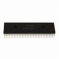
HD6473258P10 Renesas Electronics America, HD6473258P10 Datasheet - Page 34

HD6473258P10
Manufacturer Part Number
HD6473258P10
Description
IC H8 MCU OTP 32K 64DIP
Manufacturer
Renesas Electronics America
Series
H8® H8/325r
Datasheet
1.HD6413238F10.pdf
(301 pages)
Specifications of HD6473258P10
Core Processor
H8/300
Core Size
8-Bit
Speed
10MHz
Connectivity
SCI, UART/USART
Number Of I /o
53
Program Memory Size
32KB (32K x 8)
Program Memory Type
OTP
Ram Size
1K x 8
Voltage - Supply (vcc/vdd)
4.5 V ~ 5.5 V
Oscillator Type
External
Operating Temperature
-20°C ~ 75°C
Package / Case
64-DIP
Lead Free Status / RoHS Status
Contains lead / RoHS non-compliant
Eeprom Size
-
Data Converters
-
Peripherals
-
Available stocks
Company
Part Number
Manufacturer
Quantity
Price
Company:
Part Number:
HD6473258P10
Manufacturer:
EXEL
Quantity:
6 218
Company:
Part Number:
HD6473258P10V
Manufacturer:
RENESAS
Quantity:
600
Part Number:
HD6473258P10V
Manufacturer:
HITACHI/日立
Quantity:
20 000
- Current page: 34 of 301
- Download datasheet (2Mb)
2.4 Mode and System Control Registers (MDCR and SYSCR)
Two of the control registers in the register field are the mode control register (MDCR) and system
control register (SYSCR). The mode control register controls the MCU mode: the operating mode
of the H8/325 Series chip. The system control register has a bit that enables or disables the on-chip
RAM. Table 2-2 lists the attributes of these registers.
Table 2-2. Mode and System Control Registers
Name
Mode control register
System control register
2.4.1 Mode Control Register (MDCR)—H’FFC5
Bit
Initial value
Read/Write
* Initialized according to MD
Bits 7 to 5 and 2—Reserved: These bits cannot be modified and are always read as 1.
Bits 4 and 3—Reserved: These bits cannot be modified and are always read as 0.
Bits 1 and 0—Mode Select 1 and 0 (MDS1 and MDS0): These bits indicate the values of the
mode pins (MD
not written.
Coding Example: To test whether the MCU is operating in mode 1:
The comparison is with H’E5 instead of H’01 because bits 7, 6, 5, and 2 are always read as 1.
MOV.B @H’FFC5, R0L
CMP.B #H’E5, R0L
1
and MD
—
R
7
1
0
) latched on the rising edge of the RES signal. These bits can be read but
—
R
6
1
1
and MD
Abbreviation
MDCR
SYSCR
—
R
5
1
0
inputs.
24
—
R
4
0
Read/Write
R
R/W
—
R
3
0
—
R
2
1
MDS1
Address
H’FFC5
H’FFC4
R
1
*
MDS0
R
0
*
Related parts for HD6473258P10
Image
Part Number
Description
Manufacturer
Datasheet
Request
R

Part Number:
Description:
KIT STARTER FOR M16C/29
Manufacturer:
Renesas Electronics America
Datasheet:

Part Number:
Description:
KIT STARTER FOR R8C/2D
Manufacturer:
Renesas Electronics America
Datasheet:

Part Number:
Description:
R0K33062P STARTER KIT
Manufacturer:
Renesas Electronics America
Datasheet:

Part Number:
Description:
KIT STARTER FOR R8C/23 E8A
Manufacturer:
Renesas Electronics America
Datasheet:

Part Number:
Description:
KIT STARTER FOR R8C/25
Manufacturer:
Renesas Electronics America
Datasheet:

Part Number:
Description:
KIT STARTER H8S2456 SHARPE DSPLY
Manufacturer:
Renesas Electronics America
Datasheet:

Part Number:
Description:
KIT STARTER FOR R8C38C
Manufacturer:
Renesas Electronics America
Datasheet:

Part Number:
Description:
KIT STARTER FOR R8C35C
Manufacturer:
Renesas Electronics America
Datasheet:

Part Number:
Description:
KIT STARTER FOR R8CL3AC+LCD APPS
Manufacturer:
Renesas Electronics America
Datasheet:

Part Number:
Description:
KIT STARTER FOR RX610
Manufacturer:
Renesas Electronics America
Datasheet:

Part Number:
Description:
KIT STARTER FOR R32C/118
Manufacturer:
Renesas Electronics America
Datasheet:

Part Number:
Description:
KIT DEV RSK-R8C/26-29
Manufacturer:
Renesas Electronics America
Datasheet:

Part Number:
Description:
KIT STARTER FOR SH7124
Manufacturer:
Renesas Electronics America
Datasheet:

Part Number:
Description:
KIT STARTER FOR H8SX/1622
Manufacturer:
Renesas Electronics America
Datasheet:

Part Number:
Description:
KIT DEV FOR SH7203
Manufacturer:
Renesas Electronics America
Datasheet:


