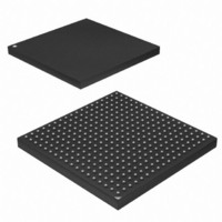
AT91SAM9263B-CU Atmel, AT91SAM9263B-CU Datasheet - Page 270

AT91SAM9263B-CU
Manufacturer Part Number
AT91SAM9263B-CU
Description
IC ARM9 MCU 200 MHZ 324-TFBGA
Manufacturer
Atmel
Series
AT91SAMr
Specifications of AT91SAM9263B-CU
Core Processor
ARM9
Core Size
16/32-Bit
Speed
240MHz
Connectivity
CAN, Ethernet, I²C, MMC, SPI, SSC, UART/USART, USB
Peripherals
AC'97, LCD, POR, PWM, WDT
Number Of I /o
160
Program Memory Size
128KB (128K x 8)
Program Memory Type
ROM
Ram Size
128K x 8
Voltage - Supply (vcc/vdd)
1.08 V ~ 1.32 V
Oscillator Type
Internal
Operating Temperature
-40°C ~ 85°C
Package / Case
324-TFBGA
Processor Series
AT91SAMx
Core
ARM926EJ-S
Data Bus Width
32 bit
Data Ram Size
96 KB
Interface Type
2-Wire, EBI, I2S, MCI, SPI, USART
Maximum Clock Frequency
200 MHz
Number Of Programmable I/os
160
Number Of Timers
4
Maximum Operating Temperature
+ 85 C
Mounting Style
SMD/SMT
3rd Party Development Tools
JTRACE-ARM-2M, MDK-ARM, RL-ARM, ULINK2
Development Tools By Supplier
AT91SAM-ICE, AT91-ISP, AT91SAM9263-EK
Minimum Operating Temperature
- 40 C
Package
324TFBGA
Device Core
ARM926EJ-S
Family Name
91S
Maximum Speed
200 MHz
Operating Supply Voltage
1.8|2.5|3.3 V
Controller Family/series
AT91SAM9xxx
No. Of I/o's
160
Ram Memory Size
96KB
Cpu Speed
240MHz
No. Of Timers
1
Rohs Compliant
Yes
For Use With
AT91SAM9263-EK - KIT EVAL FOR AT91SAM9263AT91SAM-ICE - EMULATOR FOR AT91 ARM7/ARM9
Lead Free Status / RoHS Status
Lead free / RoHS Compliant
Eeprom Size
-
Data Converters
-
Lead Free Status / Rohs Status
Lead free / RoHS Compliant
Other names
Q3735625
Available stocks
Company
Part Number
Manufacturer
Quantity
Price
Company:
Part Number:
AT91SAM9263B-CU
Manufacturer:
IDT
Quantity:
1 043
Part Number:
AT91SAM9263B-CU
Manufacturer:
ATMEL/爱特梅尔
Quantity:
20 000
Company:
Part Number:
AT91SAM9263B-CU-100
Manufacturer:
ATMEL
Quantity:
1 000
- Current page: 270 of 1110
- Download datasheet (17Mb)
only if it does not insert more than 16 wait states. If more than 16 wait states are required, then
the peripheral should use a handshaking interface (the default if the peripheral is not pro-
grammed to be memory) in order to signal when it is ready to accept or supply data.
Channel: Read/write datapath between a source peripheral on one configured AMBA layer and
a destination peripheral on the same or different AMBA layer that occurs through the channel
FIFO. If the source peripheral is not memory, then a source handshaking interface is assigned to
the channel. If the destination peripheral is not memory, then a destination handshaking inter-
face is assigned to the channel. Source and destination handshaking interfaces can be assigned
dynamically by programming the channel registers.
Master interface: DMAC is a master on the AHB bus reading data from the source and writing it
to the destination over the AHB bus.
Slave interface: The AHB interface over which the DMAC is programmed. The slave interface
in practice could be on the same layer as any of the master interfaces or on a separate layer.
Handshaking interface: A set of signal registers that conform to a protocol and handshake
between the DMAC and source or destination peripheral to control the transfer of a single or
burst transaction between them. This interface is used to request, acknowledge, and control a
DMAC transaction. A channel can receive a request through one of three types of handshaking
interface: hardware, software, or peripheral interrupt.
Hardware handshaking interface: Uses hardware signals to control the transfer of a single or
burst transaction between the DMAC and the source or destination peripheral.
Software handshaking interface: Uses software registers to control the transfer of a single or
burst transaction between the DMAC and the source or destination peripheral. No special DMAC
handshaking signals are needed on the I/O of the peripheral. This mode is useful for interfacing
an existing peripheral to the DMAC without modifying it.
Peripheral interrupt handshaking interface: A simple use of the hardware handshaking inter-
face. In this mode, the interrupt line from the peripheral is tied to the dma_req input of the
hardware handshaking interface. Other interface signals are ignored.
Flow controller: The device (either the DMAC or source/destination peripheral) that determines
the length of and terminates a DMA block transfer. If the length of a block is known before
enabling the channel, then the DMAC should be programmed as the flow controller. If the length
of a block is not known prior to enabling the channel, the source or destination peripheral needs
to terminate a block transfer. In this mode, the peripheral is the flow controller.
Flow control mode (DMAC_CFGx.FCMODE): Special mode that only applies when the desti-
nation peripheral is the flow controller. It controls the pre-fetching of data from the source
peripheral.
Transfer hierarchy:
Figure 25-2 on page 271
illustrates the hierarchy between DMAC transfers,
block transfers, transactions (single or burst), and AMBA transfers (single or burst) for non-mem-
ory peripherals.
Figure 25-3 on page 271
shows the transfer hierarchy for memory.
AT91SAM9263
270
6249H–ATARM–27-Jul-09
Related parts for AT91SAM9263B-CU
Image
Part Number
Description
Manufacturer
Datasheet
Request
R

Part Number:
Description:
MCU, MPU & DSP Development Tools KICKSTART KIT FOR AT91SAM9 PLUS
Manufacturer:
IAR Systems

Part Number:
Description:
DEV KIT FOR AVR/AVR32
Manufacturer:
Atmel
Datasheet:

Part Number:
Description:
INTERVAL AND WIPE/WASH WIPER CONTROL IC WITH DELAY
Manufacturer:
ATMEL Corporation
Datasheet:

Part Number:
Description:
Low-Voltage Voice-Switched IC for Hands-Free Operation
Manufacturer:
ATMEL Corporation
Datasheet:

Part Number:
Description:
MONOLITHIC INTEGRATED FEATUREPHONE CIRCUIT
Manufacturer:
ATMEL Corporation
Datasheet:

Part Number:
Description:
AM-FM Receiver IC U4255BM-M
Manufacturer:
ATMEL Corporation
Datasheet:

Part Number:
Description:
Monolithic Integrated Feature Phone Circuit
Manufacturer:
ATMEL Corporation
Datasheet:

Part Number:
Description:
Multistandard Video-IF and Quasi Parallel Sound Processing
Manufacturer:
ATMEL Corporation
Datasheet:

Part Number:
Description:
High-performance EE PLD
Manufacturer:
ATMEL Corporation
Datasheet:

Part Number:
Description:
8-bit Flash Microcontroller
Manufacturer:
ATMEL Corporation
Datasheet:

Part Number:
Description:
2-Wire Serial EEPROM
Manufacturer:
ATMEL Corporation
Datasheet:


