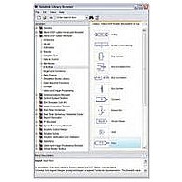
IPT-DSPBUILDER Altera, IPT-DSPBUILDER Datasheet - Page 204

IPT-DSPBUILDER
Manufacturer Part Number
IPT-DSPBUILDER
Description
DSP BUILDER SOFTWARE
Manufacturer
Altera
Type
DSPr
Datasheet
1.IPT-DSPBUILDER.pdf
(422 pages)
Specifications of IPT-DSPBUILDER
Function
DSP Builder
License
Initial License
Software Application
IP CORE, DSP BUILDER
Core Architecture
FPGA
Core Sub-architecture
Arria, Cyclone, Stratix
Supported Families
Arria GX, Arria II GX, Cyclone, Stratix
Rohs Compliant
NA
Lead Free Status / RoHS Status
Not applicable / Not applicable
- Current page: 204 of 422
- Download datasheet (6Mb)
1–14
SignalTap II Logic Analyzer
Table 1–17. SignalTap II Logic Analyzer Block Parameters Page
DSP Builder Standard Blockset Libraries
Scan JTAG
Acquire
SignalTap Nodes List of SignalTap II node
Change
Name
f
1
List of ports connected
to the JTAG cable.
blocks.
Don’t Care, High, Low,
Rising Edge, Falling
Edge, Either Edge
Use a
As programmable logic design complexity increases, system verification in software
becomes time consuming and replicating real-world stimulus is increasingly difficult.
To alleviate these problems, you can supplement traditional system verification with
efficient board-level verification.
DSP Builder supports the SignalTap
capture signal activity from internal Altera device nodes while the system under test
runs at speed. Use the SignalTap II Logic Analyzer block to set up event
triggers, configure memory, and display captured waveforms.
You use the
saved to internal embedded system blocks (ESBs) when the logic analyzer is
triggered, and are subsequently streamed off chip via the JTAG port with an Altera
download cable. The captured data is then stored in a text file, displayed as a
waveform in a MATLAB plot, and transferred to the MATLAB workspace as a global
variable.
Table 1–17
For detailed instructions on with the SignalTap II Logic Analyzer and
SignalTap II Node blocks, refer to the Performing SignalTap II Logic Analysis
chapter in the
Builder Handbook.
Value
Clock
—
shows the SignalTap II Logic Analyzer block parameters.
SignalTap II Node
or
DSP Builder Standard Blockset User Guide
Clock_Derived
The JTAG cable port.
Click to acquire data from the development board.
Click to select a node and use the Change button to set a trigger condition.
Click the Change button to set the specified logic condition as the trigger
condition for the selected node.
Preliminary
block to specify the clock and reset signals.
block to select signals to monitor. Samples are
®
II embedded logic analyzer, which lets you
Description
section in volume 2 of the DSP
© June 2010 Altera Corporation
SignalTap II Logic Analyzer
Chapter 1: AltLab Library
Related parts for IPT-DSPBUILDER
Image
Part Number
Description
Manufacturer
Datasheet
Request
R

Part Number:
Description:
CYCLONE II STARTER KIT EP2C20N
Manufacturer:
Altera
Datasheet:

Part Number:
Description:
CPLD, EP610 Family, ECMOS Process, 300 Gates, 16 Macro Cells, 16 Reg., 16 User I/Os, 5V Supply, 35 Speed Grade, 24DIP
Manufacturer:
Altera Corporation
Datasheet:

Part Number:
Description:
CPLD, EP610 Family, ECMOS Process, 300 Gates, 16 Macro Cells, 16 Reg., 16 User I/Os, 5V Supply, 15 Speed Grade, 24DIP
Manufacturer:
Altera Corporation
Datasheet:

Part Number:
Description:
Manufacturer:
Altera Corporation
Datasheet:

Part Number:
Description:
CPLD, EP610 Family, ECMOS Process, 300 Gates, 16 Macro Cells, 16 Reg., 16 User I/Os, 5V Supply, 30 Speed Grade, 24DIP
Manufacturer:
Altera Corporation
Datasheet:

Part Number:
Description:
High-performance, low-power erasable programmable logic devices with 8 macrocells, 10ns
Manufacturer:
Altera Corporation
Datasheet:

Part Number:
Description:
High-performance, low-power erasable programmable logic devices with 8 macrocells, 7ns
Manufacturer:
Altera Corporation
Datasheet:

Part Number:
Description:
Classic EPLD
Manufacturer:
Altera Corporation
Datasheet:

Part Number:
Description:
High-performance, low-power erasable programmable logic devices with 8 macrocells, 10ns
Manufacturer:
Altera Corporation
Datasheet:

Part Number:
Description:
Manufacturer:
Altera Corporation
Datasheet:

Part Number:
Description:
Manufacturer:
Altera Corporation
Datasheet:

Part Number:
Description:
Manufacturer:
Altera Corporation
Datasheet:

Part Number:
Description:
CPLD, EP610 Family, ECMOS Process, 300 Gates, 16 Macro Cells, 16 Reg., 16 User I/Os, 5V Supply, 25 Speed Grade, 24DIP
Manufacturer:
Altera Corporation
Datasheet:


