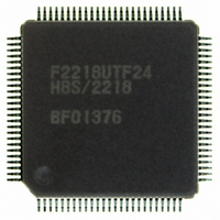
HD64F2218UTF24 Renesas Electronics America, HD64F2218UTF24 Datasheet - Page 683

HD64F2218UTF24
Manufacturer Part Number
HD64F2218UTF24
Description
IC H8S MCU FLASH 128K 100-TQFP
Manufacturer
Renesas Electronics America
Series
H8® H8S/2200r
Specifications of HD64F2218UTF24
Core Processor
H8S/2000
Core Size
16-Bit
Speed
24MHz
Connectivity
SCI, SmartCard, USB
Peripherals
DMA, POR, PWM, WDT
Number Of I /o
69
Program Memory Size
128KB (128K x 8)
Program Memory Type
FLASH
Ram Size
12K x 8
Voltage - Supply (vcc/vdd)
2.7 V ~ 3.6 V
Data Converters
A/D 6x10b
Oscillator Type
Internal
Operating Temperature
-20°C ~ 75°C
Package / Case
100-TQFP, 100-VQFP
For Use With
3DK2218-SS - KIT DEV H8S/2218 WINDOWS SIDESHW
Lead Free Status / RoHS Status
Contains lead / RoHS non-compliant
Eeprom Size
-
Available stocks
Company
Part Number
Manufacturer
Quantity
Price
Part Number:
HD64F2218UTF24V
Manufacturer:
RENESAS/瑞萨
Quantity:
20 000
- Current page: 683 of 758
- Download datasheet (5Mb)
20.10
There are three modes, high-speed, medium-speed, and subactive, in which the CPU executes
programs. When a direct transition is made, there is no interruption of program execution when
shifting between high-speed and subactive modes. Direct transitions are enabled by setting the
LPWRCR DTON bit to 1, then executing the SLEEP instruction. After a transition, direct
transition interrupt exception processing starts.
20.10.1 Direct Transitions from High-Speed Mode to Subactive Mode
Execute the SLEEP instruction in high-speed mode when the SBYCR SSBY bit = 1, LPWRCR
LSON bit = 1, and DTON bit = 1, and TSCR_1 PSS bit = 1 to make a transition to subactive
mode.
20.10.2 Direct Transitions from Subactive Mode to High-Speed Mode
Execute the SLEEP instruction in subactive mode when the SBYCR SSBY bit = 1, LPWRCR
LSON bit = 0, and DTON bit = 1, and TSCR_1 PSS bit = 1 to make a direct transition to high-
speed mode after the time set in SBYCR STS2 to STS0 has elapsed.
20.11
Output of the φ clock can be controlled by means of the PSTOP bit in SCKCR, and DDR for the
corresponding port. When the PSTOP bit is set to 1, the φ clock stops at the end of the bus cycle,
and φ output goes high. φ clock output is enabled when the PSTOP bit is cleared to 0. When DDR
for the corresponding port is cleared to 0, φ clock output is disabled and input port mode is set.
Table 20.4 shows the state of the φ pin in each processing state.
Table 20.4 φ Pin State in Each Processing State
Legend:
×: Don’t care
Register Settings
DDR
0
1
1
Direct Transitions
φ Clock Output Disabling Function
PSTOP
×
0
1
High-Speed Mode,
Medium-Speed Mode,
Subactive Mode
High impedance
φ output
Fixed high
Sleep Mode, Subsleep
Mode
High impedance
φ output
Fixed high
Rev.7.00 Dec. 24, 2008 Page 627 of 698
Software Standby
Mode, Watch Mode,
Direct Transition
High impedance
Fixed high
Fixed high
Hardware Standby
Mode
High impedance
High impedance
High impedance
REJ09B0074-0700
Related parts for HD64F2218UTF24
Image
Part Number
Description
Manufacturer
Datasheet
Request
R

Part Number:
Description:
KIT STARTER FOR M16C/29
Manufacturer:
Renesas Electronics America
Datasheet:

Part Number:
Description:
KIT STARTER FOR R8C/2D
Manufacturer:
Renesas Electronics America
Datasheet:

Part Number:
Description:
R0K33062P STARTER KIT
Manufacturer:
Renesas Electronics America
Datasheet:

Part Number:
Description:
KIT STARTER FOR R8C/23 E8A
Manufacturer:
Renesas Electronics America
Datasheet:

Part Number:
Description:
KIT STARTER FOR R8C/25
Manufacturer:
Renesas Electronics America
Datasheet:

Part Number:
Description:
KIT STARTER H8S2456 SHARPE DSPLY
Manufacturer:
Renesas Electronics America
Datasheet:

Part Number:
Description:
KIT STARTER FOR R8C38C
Manufacturer:
Renesas Electronics America
Datasheet:

Part Number:
Description:
KIT STARTER FOR R8C35C
Manufacturer:
Renesas Electronics America
Datasheet:

Part Number:
Description:
KIT STARTER FOR R8CL3AC+LCD APPS
Manufacturer:
Renesas Electronics America
Datasheet:

Part Number:
Description:
KIT STARTER FOR RX610
Manufacturer:
Renesas Electronics America
Datasheet:

Part Number:
Description:
KIT STARTER FOR R32C/118
Manufacturer:
Renesas Electronics America
Datasheet:

Part Number:
Description:
KIT DEV RSK-R8C/26-29
Manufacturer:
Renesas Electronics America
Datasheet:

Part Number:
Description:
KIT STARTER FOR SH7124
Manufacturer:
Renesas Electronics America
Datasheet:

Part Number:
Description:
KIT STARTER FOR H8SX/1622
Manufacturer:
Renesas Electronics America
Datasheet:

Part Number:
Description:
KIT DEV FOR SH7203
Manufacturer:
Renesas Electronics America
Datasheet:


