HD64F2218UTF24 Renesas Electronics America, HD64F2218UTF24 Datasheet - Page 54
HD64F2218UTF24
Manufacturer Part Number
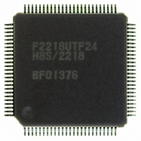
HD64F2218UTF24
Description
IC H8S MCU FLASH 128K 100-TQFP
Manufacturer
Renesas Electronics America
Series
H8® H8S/2200r
Specifications of HD64F2218UTF24
Core Processor
H8S/2000
Core Size
16-Bit
Speed
24MHz
Connectivity
SCI, SmartCard, USB
Peripherals
DMA, POR, PWM, WDT
Number Of I /o
69
Program Memory Size
128KB (128K x 8)
Program Memory Type
FLASH
Ram Size
12K x 8
Voltage - Supply (vcc/vdd)
2.7 V ~ 3.6 V
Data Converters
A/D 6x10b
Oscillator Type
Internal
Operating Temperature
-20°C ~ 75°C
Package / Case
100-TQFP, 100-VQFP
For Use With
3DK2218-SS - KIT DEV H8S/2218 WINDOWS SIDESHW
Lead Free Status / RoHS Status
Contains lead / RoHS non-compliant
Eeprom Size
-
Available stocks
Company
Part Number
Manufacturer
Quantity
Price

Part Number:
HD64F2218UTF24V
Manufacturer:
RENESAS/瑞萨
Quantity:
20 000


Table 12.9
Table 12.10 Serial Transfer Formats (Asynchronous Mode)...................................................... 404
Table 12.11 SSR Status Flags and Receive Data Handling ........................................................ 411
Table 12.12 SCI Interrupt Sources ............................................................................................. 440
Table 12.13 Interrupt Sources in Smart Card Interface Mode .................................................... 441
Section 13 Boundary Scan Function
Table 13.1
Table 13.2
Table 13.3
Table 13.4
Section 14 Universal Serial Bus (USB)
Table 14.1
Table 14.2
Table 14.3
Table 14.4
Table 14.5
Section 15 A/D Converter
Table 15.1
Table 15.2
Table 15.3
Table 15.4
Table 15.5
Table 15.6
Section 17 Flash Memory (F-ZTAT Version)
Table 17.1
Table 17.2
Table 17.3
Table 17.4
Table 17.5
Table 17.6
Table 17.7
Table 17.8
Table 17.9
Section 19 Clock Pulse Generator
Table 19.1
Rev.7.00 Dec. 24, 2008 Page lii of liv
REJ09B0074-0700
Maximum Bit Rate at Various Frequencies (Smart Card Interface Mode)............. 402
Pin Configuration.................................................................................................... 451
Instruction Configuration........................................................................................ 452
IDCODE Register Configuration............................................................................ 454
Correspondence between LSI Pins and Boundary Scan Register ........................... 455
Pin Configuration.................................................................................................... 467
Relationship between UTSTR0 Setting and Pin Output ......................................... 490
Relationship between Pin Input and UTSTR1 Monitoring Value .......................... 491
Interrupt Sources..................................................................................................... 495
Command Decoding by Firmware.......................................................................... 516
Pin Configuration.................................................................................................... 537
Analog Input Channels and Corresponding ADDR Registers ................................ 538
A/D Conversion Time (Single Mode)..................................................................... 545
A/D Conversion Time (Scan Mode) ....................................................................... 545
A/D Converter Interrupt Source.............................................................................. 546
Analog Pin Specifications....................................................................................... 549
Differences between Boot Mode and User Program Mode .................................... 555
Pin Configuration.................................................................................................... 561
Setting On-Board Programming Modes ................................................................. 567
Boot Mode Operation ............................................................................................. 570
System Clock Frequencies for which Automatic Adjustment of LSI Bit Rate Is
Possible................................................................................................................... 570
Enumeration Information........................................................................................ 571
USB Boot Mode Operation..................................................................................... 574
Flash Memory Operating States.............................................................................. 586
Registers Present in F-ZTAT Version but Absent in Masked ROM Version......... 592
Damping Resistance Value..................................................................................... 600
Related parts for HD64F2218UTF24
Image
Part Number
Description
Manufacturer
Datasheet
Request
R

Part Number:
Description:
KIT STARTER FOR M16C/29
Manufacturer:
Renesas Electronics America
Datasheet:

Part Number:
Description:
KIT STARTER FOR R8C/2D
Manufacturer:
Renesas Electronics America
Datasheet:

Part Number:
Description:
R0K33062P STARTER KIT
Manufacturer:
Renesas Electronics America
Datasheet:

Part Number:
Description:
KIT STARTER FOR R8C/23 E8A
Manufacturer:
Renesas Electronics America
Datasheet:

Part Number:
Description:
KIT STARTER FOR R8C/25
Manufacturer:
Renesas Electronics America
Datasheet:

Part Number:
Description:
KIT STARTER H8S2456 SHARPE DSPLY
Manufacturer:
Renesas Electronics America
Datasheet:

Part Number:
Description:
KIT STARTER FOR R8C38C
Manufacturer:
Renesas Electronics America
Datasheet:

Part Number:
Description:
KIT STARTER FOR R8C35C
Manufacturer:
Renesas Electronics America
Datasheet:

Part Number:
Description:
KIT STARTER FOR R8CL3AC+LCD APPS
Manufacturer:
Renesas Electronics America
Datasheet:
Part Number:
Description:
KIT STARTER FOR RX610
Manufacturer:
Renesas Electronics America
Datasheet:

Part Number:
Description:
KIT STARTER FOR R32C/118
Manufacturer:
Renesas Electronics America
Datasheet:

Part Number:
Description:
KIT DEV RSK-R8C/26-29
Manufacturer:
Renesas Electronics America
Datasheet:

Part Number:
Description:
KIT STARTER FOR SH7124
Manufacturer:
Renesas Electronics America
Datasheet:

Part Number:
Description:
KIT STARTER FOR H8SX/1622
Manufacturer:
Renesas Electronics America
Datasheet:

Part Number:
Description:
KIT DEV FOR SH7203
Manufacturer:
Renesas Electronics America
Datasheet: