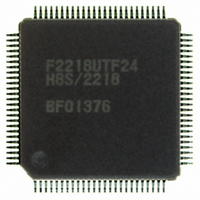
HD64F2218UTF24 Renesas Electronics America, HD64F2218UTF24 Datasheet - Page 587

HD64F2218UTF24
Manufacturer Part Number
HD64F2218UTF24
Description
IC H8S MCU FLASH 128K 100-TQFP
Manufacturer
Renesas Electronics America
Series
H8® H8S/2200r
Specifications of HD64F2218UTF24
Core Processor
H8S/2000
Core Size
16-Bit
Speed
24MHz
Connectivity
SCI, SmartCard, USB
Peripherals
DMA, POR, PWM, WDT
Number Of I /o
69
Program Memory Size
128KB (128K x 8)
Program Memory Type
FLASH
Ram Size
12K x 8
Voltage - Supply (vcc/vdd)
2.7 V ~ 3.6 V
Data Converters
A/D 6x10b
Oscillator Type
Internal
Operating Temperature
-20°C ~ 75°C
Package / Case
100-TQFP, 100-VQFP
For Use With
3DK2218-SS - KIT DEV H8S/2218 WINDOWS SIDESHW
Lead Free Status / RoHS Status
Contains lead / RoHS non-compliant
Eeprom Size
-
Available stocks
Company
Part Number
Manufacturer
Quantity
Price
Part Number:
HD64F2218UTF24V
Manufacturer:
RENESAS/瑞萨
Quantity:
20 000
- Current page: 587 of 758
- Download datasheet (5Mb)
Note: * Interrupts should be masked from when the IRQ6 interrupt is received until the SLEEP instruction is executed.
(1)
(2)
(3)
(4)
(5)
(6)
(7)
(8)
(9)
Guide to Flowchart Figures
Unmask all interrupts with LDC instruction, etc.*
Finally, unmask the interrupts using the LDC instruction or the like and execute the SLEEP instruction immediately
afterward.
Mask all interrupts with LDC instruction, etc.*
Procedure to enter power-down mode
Specify IRQ6 to falling edge sensitive
Set SPRSi and SPRSs in UIFR3 to 1
(Stop MSTPB0 in MSTPCRB to 1)
All USB module internal clocks stop
IRQ6 = Low (falling edge output)
(Write IRQ6SCB and IRQ6SCA
Detect USB bus suspend state
Enter USB module stop 2 state
Confirm SPRSs in UIFR3 as 1
(Execute SLEEP instruction)
Clear SPRSi in UIFR3 to 0
Enter power-down mode*
Clear IRQ6E in IER to 0 *
All LSI internal clocks stop
: Indicates operations to be done
: Indicates operations to be
(Set IRQ6E in IER to 1)
Set IRQ6E in IER to 1*
Set IRQ6F in ISR to 1
by firmware.
automatically done by hardware
in this LSI.
USPND pin = High
in ISCRH to 01
IRQ6 = High
Figure 14.28 Flowchart
(10)
(11)
(12)
(13)
(14)
(15)
(16)
(17)
(18)
(19)
(20)
(21)
(22)
(23)
(24)
Rev.7.00 Dec. 24, 2008 Page 531 of 698
Procedure to cancel power-down mode
restarted by using various USB registers
USB communication operations can be
Wait for system clock stabilization time
(Wait for CK48READY in UIFR3 is set to 1)
(For crystal oscillator clock: 4 ms min.)
USB module intenal clock operation starts
(LSI internal clock starts oscillation)
(Clear MSTPB0 in MSTPCRB to 0)
(For external clok: 16 states min.)
Wait 2 ms for USB operation clock
IRQ6 = Low (falling edge output)
Cancel USB module stop2 mode
(USB operating clock stabilized)
Set CK48READY in UIFR3 to 1
Clear SPRSs of UIFR3 to 0
Clear SPRSi in UIFR3 to 0
Cancel power-down mode
Set SPRSi of UIFR3 to 1
Detect USB bus resume
Set SOF of UIFR3 to 1
Set IRQ6F in ISR to 1
Detect SOF packet
USPND pin = Low
Enter active mode
IRQ6 = High
to stabilize
REJ09B0074-0700
Related parts for HD64F2218UTF24
Image
Part Number
Description
Manufacturer
Datasheet
Request
R

Part Number:
Description:
KIT STARTER FOR M16C/29
Manufacturer:
Renesas Electronics America
Datasheet:

Part Number:
Description:
KIT STARTER FOR R8C/2D
Manufacturer:
Renesas Electronics America
Datasheet:

Part Number:
Description:
R0K33062P STARTER KIT
Manufacturer:
Renesas Electronics America
Datasheet:

Part Number:
Description:
KIT STARTER FOR R8C/23 E8A
Manufacturer:
Renesas Electronics America
Datasheet:

Part Number:
Description:
KIT STARTER FOR R8C/25
Manufacturer:
Renesas Electronics America
Datasheet:

Part Number:
Description:
KIT STARTER H8S2456 SHARPE DSPLY
Manufacturer:
Renesas Electronics America
Datasheet:

Part Number:
Description:
KIT STARTER FOR R8C38C
Manufacturer:
Renesas Electronics America
Datasheet:

Part Number:
Description:
KIT STARTER FOR R8C35C
Manufacturer:
Renesas Electronics America
Datasheet:

Part Number:
Description:
KIT STARTER FOR R8CL3AC+LCD APPS
Manufacturer:
Renesas Electronics America
Datasheet:

Part Number:
Description:
KIT STARTER FOR RX610
Manufacturer:
Renesas Electronics America
Datasheet:

Part Number:
Description:
KIT STARTER FOR R32C/118
Manufacturer:
Renesas Electronics America
Datasheet:

Part Number:
Description:
KIT DEV RSK-R8C/26-29
Manufacturer:
Renesas Electronics America
Datasheet:

Part Number:
Description:
KIT STARTER FOR SH7124
Manufacturer:
Renesas Electronics America
Datasheet:

Part Number:
Description:
KIT STARTER FOR H8SX/1622
Manufacturer:
Renesas Electronics America
Datasheet:

Part Number:
Description:
KIT DEV FOR SH7203
Manufacturer:
Renesas Electronics America
Datasheet:


