HD64F2218UTF24 Renesas Electronics America, HD64F2218UTF24 Datasheet - Page 629
HD64F2218UTF24
Manufacturer Part Number
HD64F2218UTF24
Description
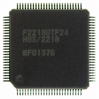
IC H8S MCU FLASH 128K 100-TQFP
Manufacturer
Renesas Electronics America
Series
H8® H8S/2200r
Specifications of HD64F2218UTF24
Core Processor
H8S/2000
Core Size
16-Bit
Speed
24MHz
Connectivity
SCI, SmartCard, USB
Peripherals
DMA, POR, PWM, WDT
Number Of I /o
69
Program Memory Size
128KB (128K x 8)
Program Memory Type
FLASH
Ram Size
12K x 8
Voltage - Supply (vcc/vdd)
2.7 V ~ 3.6 V
Data Converters
A/D 6x10b
Oscillator Type
Internal
Operating Temperature
-20°C ~ 75°C
Package / Case
100-TQFP, 100-VQFP
For Use With
3DK2218-SS - KIT DEV H8S/2218 WINDOWS SIDESHW
Lead Free Status / RoHS Status
Contains lead / RoHS non-compliant
Eeprom Size
-
Available stocks
Company
Part Number
Manufacturer
Quantity
Price

Part Number:
HD64F2218UTF24V
Manufacturer:
RENESAS/瑞萨
Quantity:
20 000


3. Set the frequency for transmission from the host as a numeric value in units of MHz × 100 (ex:
4. In boot mode, the 4-kbyte on-chip RAM area H'FFE000 to H'FFEFBF is used by the boot
5. When a branch is made to the programming control program, the USB remains connected and
6. Boot mode is by means of a reset. Drive the reset pin low, wait for the elapse of at least 20
7. Do not change the input level of the mode pins while in boot mode. In the input level of a
8. Interrupt cannot be used during flash memory programming or erasing.
Note: * FWE pin and mode pin input must satisfy the mode programming set up time (t
16.00 MHz → H'0640, 24.00 MHz → H'0960).
program. The programming control program is transferred from the host stored in the 8-kbyte
area H'FFC000 to H'FFDFFF in the HD64F2218U, HD64F2218CU, HD64F2212U, and
HD64F2212CU and the 4-kbyte area H'FFD000 to H'FFDFFF in the HD64F2211U,
HD64F2211CU and HD64F2210CU. The boot program area cannot be used until program
execution switches to the programming control program. Also note that the boot program
remains in RAM even after control passes to the programming control program.
can be used immediately for transmission/reception of write data or verify data between the
programming control program and the host. The contents of CPU general registers are
undefined after a branch to the programming control program. Note, in particular, that since the
stack pointer is used implicitly in subroutine calls ad the like, it should be initialized at the start
of the programming control program.
states, then set the FWE pin and mode pins to release the reset.* Boot mode is also exited in
the event of a WDT overflow reset.
mode pin is changed (from low to high) during a reset, the states of ports with a dual function
as address output s, and bus control output signals (AS, RD, WR), will change due to switching
of the operating mode. Either make pin settings so that these pins do not become output signal
pins during a reset, or take precautions to prevent collisions with external signals.
200 ns) when a reset is released.
Rev.7.00 Dec. 24, 2008 Page 573 of 698
REJ09B0074-0700
MDS
=
Related parts for HD64F2218UTF24
Image
Part Number
Description
Manufacturer
Datasheet
Request
R

Part Number:
Description:
KIT STARTER FOR M16C/29
Manufacturer:
Renesas Electronics America
Datasheet:

Part Number:
Description:
KIT STARTER FOR R8C/2D
Manufacturer:
Renesas Electronics America
Datasheet:

Part Number:
Description:
R0K33062P STARTER KIT
Manufacturer:
Renesas Electronics America
Datasheet:

Part Number:
Description:
KIT STARTER FOR R8C/23 E8A
Manufacturer:
Renesas Electronics America
Datasheet:

Part Number:
Description:
KIT STARTER FOR R8C/25
Manufacturer:
Renesas Electronics America
Datasheet:

Part Number:
Description:
KIT STARTER H8S2456 SHARPE DSPLY
Manufacturer:
Renesas Electronics America
Datasheet:

Part Number:
Description:
KIT STARTER FOR R8C38C
Manufacturer:
Renesas Electronics America
Datasheet:

Part Number:
Description:
KIT STARTER FOR R8C35C
Manufacturer:
Renesas Electronics America
Datasheet:

Part Number:
Description:
KIT STARTER FOR R8CL3AC+LCD APPS
Manufacturer:
Renesas Electronics America
Datasheet:
Part Number:
Description:
KIT STARTER FOR RX610
Manufacturer:
Renesas Electronics America
Datasheet:

Part Number:
Description:
KIT STARTER FOR R32C/118
Manufacturer:
Renesas Electronics America
Datasheet:

Part Number:
Description:
KIT DEV RSK-R8C/26-29
Manufacturer:
Renesas Electronics America
Datasheet:

Part Number:
Description:
KIT STARTER FOR SH7124
Manufacturer:
Renesas Electronics America
Datasheet:

Part Number:
Description:
KIT STARTER FOR H8SX/1622
Manufacturer:
Renesas Electronics America
Datasheet:

Part Number:
Description:
KIT DEV FOR SH7203
Manufacturer:
Renesas Electronics America
Datasheet: