HD64F7051SFJ20V Renesas Electronics America, HD64F7051SFJ20V Datasheet - Page 90
HD64F7051SFJ20V
Manufacturer Part Number
HD64F7051SFJ20V
Description
MCU 5V 256K J-TEMP PB-FREE QFP-1
Manufacturer
Renesas Electronics America
Series
SuperH® SH7050r
Datasheet
1.HD64F7050SFJ20V.pdf
(843 pages)
Specifications of HD64F7051SFJ20V
Core Processor
SH-2
Core Size
32-Bit
Speed
20MHz
Connectivity
EBI/EMI, SCI
Peripherals
DMA, WDT
Number Of I /o
102
Program Memory Size
256KB (256K x 8)
Program Memory Type
FLASH
Ram Size
10K x 8
Voltage - Supply (vcc/vdd)
4.5 V ~ 5.5 V
Data Converters
A/D 16x10b
Oscillator Type
Internal
Operating Temperature
-40°C ~ 85°C
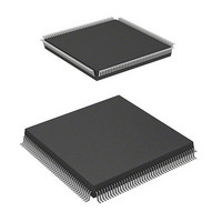
Package / Case
168-QFP
Lead Free Status / RoHS Status
Lead free / RoHS Compliant
Eeprom Size
-
Available stocks
Company
Part Number
Manufacturer
Quantity
Price
Company:

Part Number:
HD64F7051SFJ20V
Manufacturer:
RENESAS
Quantity:
101
Part Number:
HD64F7051SFJ20V
Manufacturer:
RENESAS/瑞萨
Quantity:
20 000


Section 5 Exception Processing
5.4.2
The interrupt priority order is predetermined. When multiple interrupts occur simultaneously
(overlap), the interrupt controller (INTC) determines their relative priorities and starts up
processing according to the results.
The priority order of interrupts is expressed as priority levels 0–16, with priority 0 the lowest and
priority 16 the highest. The NMI interrupt has priority 16 and cannot be masked, so it is always
accepted. The user break interrupt priority level is 15. IRQ interrupts and on-chip peripheral
module interrupt priority levels can be set freely using the INTC’s interrupt priority level setting
registers A through H (IPRA to IPRH) as shown in table 5.7. The priority levels that can be set are
0–15. Level 16 cannot be set.
Table 5.7
Type
NMI
User break
IRQ
On-chip peripheral module
5.4.3
When an interrupt occurs, its priority level is ascertained by the interrupt controller (INTC). NMI
is always accepted, but other interrupts are only accepted if they have a priority level higher than
the priority level set in the interrupt mask bits (I3–I0) of the status register (SR).
When an interrupt is accepted, exception processing begins. In interrupt exception processing, the
CPU saves SR and the program counter (PC) to the stack. The priority level value of the accepted
interrupt is written to SR bits I3–I0. For NMI, however, the priority level is 16, but the value set in
I3–I0 is H'F (level 15). Next, the start address of the exception service routine is fetched from the
exception processing vector table for the accepted interrupt, that address is jumped to and
execution begins.
Rev. 5.00 Jan 06, 2006 page 68 of 818
REJ09B0273-0500
Interrupt Priority Level
Interrupt Exception Processing
Interrupt Priority Order
Priority Level
16
15
0–15
0–15
Comment
Fixed priority level. Cannot be masked.
Fixed priority level.
Set with interrupt priority level setting registers A
through H (IPRA to IPRH).
Set with interrupt priority level setting registers A
through H (IPRA to IPRH).
Related parts for HD64F7051SFJ20V
Image
Part Number
Description
Manufacturer
Datasheet
Request
R

Part Number:
Description:
KIT STARTER FOR M16C/29
Manufacturer:
Renesas Electronics America
Datasheet:

Part Number:
Description:
KIT STARTER FOR R8C/2D
Manufacturer:
Renesas Electronics America
Datasheet:

Part Number:
Description:
R0K33062P STARTER KIT
Manufacturer:
Renesas Electronics America
Datasheet:

Part Number:
Description:
KIT STARTER FOR R8C/23 E8A
Manufacturer:
Renesas Electronics America
Datasheet:

Part Number:
Description:
KIT STARTER FOR R8C/25
Manufacturer:
Renesas Electronics America
Datasheet:

Part Number:
Description:
KIT STARTER H8S2456 SHARPE DSPLY
Manufacturer:
Renesas Electronics America
Datasheet:

Part Number:
Description:
KIT STARTER FOR R8C38C
Manufacturer:
Renesas Electronics America
Datasheet:

Part Number:
Description:
KIT STARTER FOR R8C35C
Manufacturer:
Renesas Electronics America
Datasheet:

Part Number:
Description:
KIT STARTER FOR R8CL3AC+LCD APPS
Manufacturer:
Renesas Electronics America
Datasheet:
Part Number:
Description:
KIT STARTER FOR RX610
Manufacturer:
Renesas Electronics America
Datasheet:

Part Number:
Description:
KIT STARTER FOR R32C/118
Manufacturer:
Renesas Electronics America
Datasheet:

Part Number:
Description:
KIT DEV RSK-R8C/26-29
Manufacturer:
Renesas Electronics America
Datasheet:

Part Number:
Description:
KIT STARTER FOR SH7124
Manufacturer:
Renesas Electronics America
Datasheet:

Part Number:
Description:
KIT STARTER FOR H8SX/1622
Manufacturer:
Renesas Electronics America
Datasheet:

Part Number:
Description:
KIT DEV FOR SH7203
Manufacturer:
Renesas Electronics America
Datasheet: