HD64F7051SFJ20V Renesas Electronics America, HD64F7051SFJ20V Datasheet - Page 217
HD64F7051SFJ20V
Manufacturer Part Number
HD64F7051SFJ20V
Description
MCU 5V 256K J-TEMP PB-FREE QFP-1
Manufacturer
Renesas Electronics America
Series
SuperH® SH7050r
Datasheet
1.HD64F7050SFJ20V.pdf
(843 pages)
Specifications of HD64F7051SFJ20V
Core Processor
SH-2
Core Size
32-Bit
Speed
20MHz
Connectivity
EBI/EMI, SCI
Peripherals
DMA, WDT
Number Of I /o
102
Program Memory Size
256KB (256K x 8)
Program Memory Type
FLASH
Ram Size
10K x 8
Voltage - Supply (vcc/vdd)
4.5 V ~ 5.5 V
Data Converters
A/D 16x10b
Oscillator Type
Internal
Operating Temperature
-40°C ~ 85°C
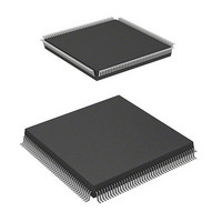
Package / Case
168-QFP
Lead Free Status / RoHS Status
Lead free / RoHS Compliant
Eeprom Size
-
Available stocks
Company
Part Number
Manufacturer
Quantity
Price
Company:

Part Number:
HD64F7051SFJ20V
Manufacturer:
RENESAS
Quantity:
101
Part Number:
HD64F7051SFJ20V
Manufacturer:
RENESAS/瑞萨
Quantity:
20 000


10.1
The SH7050 series has an on-chip advanced timer unit (ATU) with one 32-bit timer channel and
nine 16-bit timer channels.
10.1.1
ATU features are summarized below.
Capability to process up to 34 pulse inputs and outputs
Prescaler
Channel 0 has four 32-bit input capture lines, allowing the following operations:
Channels 1 and 2 have a total of eight 16-bit input capture/output compare registers and one
dedicated input capture register. The 16-bit output compare registers can also be selected for
channel 10 one-shot pulse offset.
Channels 3 to 5 have a total of ten 16-bit input capture/output compare/PWM registers (ten
inputs/outputs when using input capture/output compare, seven outputs when using PWM),
allowing the following operations:
Input clock to channel 0 scaled in 1 stage, input clock to channels 1 to 9 scaled in 2 stages
1/1 to 1/32 clock scaling possible in initial stage for all channels
1/1, 1/2, 1/4, 1/8, 1/16, or 1/32 scaling possible in second stage for channels 1 to 10
External clock TCLKA, TCLKB selection also possible for channels 1 to 5
Rising-edge, falling-edge, or both-edge detection selectable
Channel 1 compare-match can be used as capture signal (TRG1A) (ICR0A, ICR0D only)
Interrupt can be generated by trigger input
Interval interrupt generation function generates four interval interrupts as selected
Waveform output by means of compare-match: Selection of 0 output, 1 output, or toggle
output
Input capture function: Rising-edge, falling-edge, or both-edge detection
OSBR trigger source is channel 0 capture set to 1 (TRG0A)
Eight counter overflow interrupts/compare-match interrupts/capture interrupts can be
generated (channel 1/A–F, channel 2/A, B)
Compare-match signal (TRG1A) can be sent from channel 1 to channel 0 as a trigger
Compare-match signal can be sent from channel 2 to the advanced pulse controller (APC)
Selection of input capture, output compare, PWM mode
Overview
Features
Section 10 Advanced Timer Unit (ATU)
Rev. 5.00 Jan 06, 2006 page 195 of 818
Section 10 Advanced Timer Unit (ATU)
REJ09B0273-0500
Related parts for HD64F7051SFJ20V
Image
Part Number
Description
Manufacturer
Datasheet
Request
R

Part Number:
Description:
KIT STARTER FOR M16C/29
Manufacturer:
Renesas Electronics America
Datasheet:

Part Number:
Description:
KIT STARTER FOR R8C/2D
Manufacturer:
Renesas Electronics America
Datasheet:

Part Number:
Description:
R0K33062P STARTER KIT
Manufacturer:
Renesas Electronics America
Datasheet:

Part Number:
Description:
KIT STARTER FOR R8C/23 E8A
Manufacturer:
Renesas Electronics America
Datasheet:

Part Number:
Description:
KIT STARTER FOR R8C/25
Manufacturer:
Renesas Electronics America
Datasheet:

Part Number:
Description:
KIT STARTER H8S2456 SHARPE DSPLY
Manufacturer:
Renesas Electronics America
Datasheet:

Part Number:
Description:
KIT STARTER FOR R8C38C
Manufacturer:
Renesas Electronics America
Datasheet:

Part Number:
Description:
KIT STARTER FOR R8C35C
Manufacturer:
Renesas Electronics America
Datasheet:

Part Number:
Description:
KIT STARTER FOR R8CL3AC+LCD APPS
Manufacturer:
Renesas Electronics America
Datasheet:
Part Number:
Description:
KIT STARTER FOR RX610
Manufacturer:
Renesas Electronics America
Datasheet:

Part Number:
Description:
KIT STARTER FOR R32C/118
Manufacturer:
Renesas Electronics America
Datasheet:

Part Number:
Description:
KIT DEV RSK-R8C/26-29
Manufacturer:
Renesas Electronics America
Datasheet:

Part Number:
Description:
KIT STARTER FOR SH7124
Manufacturer:
Renesas Electronics America
Datasheet:

Part Number:
Description:
KIT STARTER FOR H8SX/1622
Manufacturer:
Renesas Electronics America
Datasheet:

Part Number:
Description:
KIT DEV FOR SH7203
Manufacturer:
Renesas Electronics America
Datasheet: