HD64F7051SFJ20V Renesas Electronics America, HD64F7051SFJ20V Datasheet - Page 478
HD64F7051SFJ20V
Manufacturer Part Number
HD64F7051SFJ20V
Description
MCU 5V 256K J-TEMP PB-FREE QFP-1
Manufacturer
Renesas Electronics America
Series
SuperH® SH7050r
Datasheet
1.HD64F7050SFJ20V.pdf
(843 pages)
Specifications of HD64F7051SFJ20V
Core Processor
SH-2
Core Size
32-Bit
Speed
20MHz
Connectivity
EBI/EMI, SCI
Peripherals
DMA, WDT
Number Of I /o
102
Program Memory Size
256KB (256K x 8)
Program Memory Type
FLASH
Ram Size
10K x 8
Voltage - Supply (vcc/vdd)
4.5 V ~ 5.5 V
Data Converters
A/D 16x10b
Oscillator Type
Internal
Operating Temperature
-40°C ~ 85°C
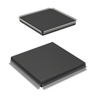
Package / Case
168-QFP
Lead Free Status / RoHS Status
Lead free / RoHS Compliant
Eeprom Size
-
Available stocks
Company
Part Number
Manufacturer
Quantity
Price
Company:

Part Number:
HD64F7051SFJ20V
Manufacturer:
RENESAS
Quantity:
101
Part Number:
HD64F7051SFJ20V
Manufacturer:
RENESAS/瑞萨
Quantity:
20 000


Section 14 A/D Converter
14.5
The A/D converter can generate an A/D conversion end interrupt request (ADI0 or ADI1) upon
completion of A/D conversions. The ADI interrupt can be enabled by setting the ADIE bit in the
A/D control/status register (ADCSR) to 1, or disabled by clearing the ADIE bit to 0.
The DMAC can be activated by an ADI interrupt. In this case an interrupt request is not sent to the
CPU.
When the DMAC is activated by an ADI interrupt, the ADF bit in ADCSR is automatically
cleared when data is transferred by the DMAC.
See section 9.4.3, Example of DMA Transfer between A/D Converter and Internal Memory, for an
example of this operation.
14.6
The following points should be noted when using the A/D converter.
1. Analog input voltage range
2. Relation between AV
3. AV
4. Notes on board design
Rev. 5.00 Jan 06, 2006 page 456 of 818
REJ09B0273-0500
The voltage applied to analog input pins during A/D conversion should be in the range AV
ANn
When using the A/D converter, set AV
converter is not used, set AV
Set AV
If conditions 1, 2, and 3 above are not met, the reliability of the device may be adversely
affected.
In board design, digital circuitry and analog circuitry should be as mutually isolated as
possible, and layout in which digital circuit signal lines and analog circuit signal lines cross or
are in close proximity should be avoided as far as possible. Failure to do so may result in
incorrect operation of the analog circuitry due to inductance, adversely affecting A/D
conversion values.
Also, digital circuitry must be isolated from the analog input signals (ANn), analog reference
voltage (AV
should be connected at one point to a stable digital ground (V
ref
input range
Interrupt Sources and DMA Transfer Requests
Usage Notes
ref
AV
= 4.5 V to AV
ref
ref
.
), and analog power supply (AV
CC
, AV
CC
when the A/D converter is used, and AV
SS
SS
and V
= V
SS
CC
, and do not leave the AV
, V
CC
SS
= V
CC
CC
±10%, and AV
) by the analog ground (AV
SS
SS
CC
) on the board.
= V
pin open.
ref
SS
. When the A/D
AV
CC
SS
when not used..
). The AV
SS
SS
Related parts for HD64F7051SFJ20V
Image
Part Number
Description
Manufacturer
Datasheet
Request
R

Part Number:
Description:
KIT STARTER FOR M16C/29
Manufacturer:
Renesas Electronics America
Datasheet:

Part Number:
Description:
KIT STARTER FOR R8C/2D
Manufacturer:
Renesas Electronics America
Datasheet:

Part Number:
Description:
R0K33062P STARTER KIT
Manufacturer:
Renesas Electronics America
Datasheet:

Part Number:
Description:
KIT STARTER FOR R8C/23 E8A
Manufacturer:
Renesas Electronics America
Datasheet:

Part Number:
Description:
KIT STARTER FOR R8C/25
Manufacturer:
Renesas Electronics America
Datasheet:

Part Number:
Description:
KIT STARTER H8S2456 SHARPE DSPLY
Manufacturer:
Renesas Electronics America
Datasheet:

Part Number:
Description:
KIT STARTER FOR R8C38C
Manufacturer:
Renesas Electronics America
Datasheet:

Part Number:
Description:
KIT STARTER FOR R8C35C
Manufacturer:
Renesas Electronics America
Datasheet:

Part Number:
Description:
KIT STARTER FOR R8CL3AC+LCD APPS
Manufacturer:
Renesas Electronics America
Datasheet:
Part Number:
Description:
KIT STARTER FOR RX610
Manufacturer:
Renesas Electronics America
Datasheet:

Part Number:
Description:
KIT STARTER FOR R32C/118
Manufacturer:
Renesas Electronics America
Datasheet:

Part Number:
Description:
KIT DEV RSK-R8C/26-29
Manufacturer:
Renesas Electronics America
Datasheet:

Part Number:
Description:
KIT STARTER FOR SH7124
Manufacturer:
Renesas Electronics America
Datasheet:

Part Number:
Description:
KIT STARTER FOR H8SX/1622
Manufacturer:
Renesas Electronics America
Datasheet:

Part Number:
Description:
KIT DEV FOR SH7203
Manufacturer:
Renesas Electronics America
Datasheet: