HD64F7051SFJ20V Renesas Electronics America, HD64F7051SFJ20V Datasheet - Page 404
HD64F7051SFJ20V
Manufacturer Part Number
HD64F7051SFJ20V
Description
MCU 5V 256K J-TEMP PB-FREE QFP-1
Manufacturer
Renesas Electronics America
Series
SuperH® SH7050r
Datasheet
1.HD64F7050SFJ20V.pdf
(843 pages)
Specifications of HD64F7051SFJ20V
Core Processor
SH-2
Core Size
32-Bit
Speed
20MHz
Connectivity
EBI/EMI, SCI
Peripherals
DMA, WDT
Number Of I /o
102
Program Memory Size
256KB (256K x 8)
Program Memory Type
FLASH
Ram Size
10K x 8
Voltage - Supply (vcc/vdd)
4.5 V ~ 5.5 V
Data Converters
A/D 16x10b
Oscillator Type
Internal
Operating Temperature
-40°C ~ 85°C
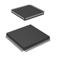
Package / Case
168-QFP
Lead Free Status / RoHS Status
Lead free / RoHS Compliant
Eeprom Size
-
Available stocks
Company
Part Number
Manufacturer
Quantity
Price
Company:

Part Number:
HD64F7051SFJ20V
Manufacturer:
RENESAS
Quantity:
101
Part Number:
HD64F7051SFJ20V
Manufacturer:
RENESAS/瑞萨
Quantity:
20 000


Section 13 Serial Communication Interface (SCI)
Bit 5—Overrun Error (ORER): Indicates that data reception ended abnormally due to an
overrun error.
Bit 5: ORER
0
1
Bit 4—Framing Error (FER): Indicates that data reception ended abnormally due to a framing
error in the asynchronous mode.
Bit 4: FER
0
1
Rev. 5.00 Jan 06, 2006 page 382 of 818
REJ09B0273-0500
Description
Receiving is in progress or has ended normally (initial value). Clearing the RE bit
to 0 in the serial control register does not affect the ORER bit, which retains its
previous value.
ORER is cleared to 0 when the chip is power-on reset or enters standby mode or
software reads ORER after it has been set to 1, then writes 0 in ORER
A receive overrun error occurred. RDR continues to hold the data received
before the overrun error, so subsequent receive data is lost. Serial receiving
cannot continue while ORER is set to 1. In the clock synchronous mode, serial
transmitting is disabled.
ORER is set to 1 if reception of the next serial data ends when RDRF is set to 1
Description
Receiving is in progress or has ended normally (initial value). Clearing the RE bit
to 0 in the serial control register does not affect the FER bit, which retains its
previous value.
FER is cleared to 0 when the chip is power-on reset or enters standby mode or
software reads FER after it has been set to 1, then writes 0 in FER
A receive framing error occurred. When the stop bit length is two bits, only the
first bit is checked to see if it is a 1. The second stop bit is not checked. When a
framing error occurs, the SCI transfers the receive data into the RDR but does
not set RDRF. Serial receiving cannot continue while FER is set to 1. In the clock
synchronous mode, serial transmitting is also disabled.
FER is set to 1 if the stop bit at the end of receive data is checked and found to
be 0
Related parts for HD64F7051SFJ20V
Image
Part Number
Description
Manufacturer
Datasheet
Request
R

Part Number:
Description:
KIT STARTER FOR M16C/29
Manufacturer:
Renesas Electronics America
Datasheet:

Part Number:
Description:
KIT STARTER FOR R8C/2D
Manufacturer:
Renesas Electronics America
Datasheet:

Part Number:
Description:
R0K33062P STARTER KIT
Manufacturer:
Renesas Electronics America
Datasheet:

Part Number:
Description:
KIT STARTER FOR R8C/23 E8A
Manufacturer:
Renesas Electronics America
Datasheet:

Part Number:
Description:
KIT STARTER FOR R8C/25
Manufacturer:
Renesas Electronics America
Datasheet:

Part Number:
Description:
KIT STARTER H8S2456 SHARPE DSPLY
Manufacturer:
Renesas Electronics America
Datasheet:

Part Number:
Description:
KIT STARTER FOR R8C38C
Manufacturer:
Renesas Electronics America
Datasheet:

Part Number:
Description:
KIT STARTER FOR R8C35C
Manufacturer:
Renesas Electronics America
Datasheet:

Part Number:
Description:
KIT STARTER FOR R8CL3AC+LCD APPS
Manufacturer:
Renesas Electronics America
Datasheet:
Part Number:
Description:
KIT STARTER FOR RX610
Manufacturer:
Renesas Electronics America
Datasheet:

Part Number:
Description:
KIT STARTER FOR R32C/118
Manufacturer:
Renesas Electronics America
Datasheet:

Part Number:
Description:
KIT DEV RSK-R8C/26-29
Manufacturer:
Renesas Electronics America
Datasheet:

Part Number:
Description:
KIT STARTER FOR SH7124
Manufacturer:
Renesas Electronics America
Datasheet:

Part Number:
Description:
KIT STARTER FOR H8SX/1622
Manufacturer:
Renesas Electronics America
Datasheet:

Part Number:
Description:
KIT DEV FOR SH7203
Manufacturer:
Renesas Electronics America
Datasheet: