HD64F7051SFJ20V Renesas Electronics America, HD64F7051SFJ20V Datasheet - Page 21
HD64F7051SFJ20V
Manufacturer Part Number
HD64F7051SFJ20V
Description
MCU 5V 256K J-TEMP PB-FREE QFP-1
Manufacturer
Renesas Electronics America
Series
SuperH® SH7050r
Datasheet
1.HD64F7050SFJ20V.pdf
(843 pages)
Specifications of HD64F7051SFJ20V
Core Processor
SH-2
Core Size
32-Bit
Speed
20MHz
Connectivity
EBI/EMI, SCI
Peripherals
DMA, WDT
Number Of I /o
102
Program Memory Size
256KB (256K x 8)
Program Memory Type
FLASH
Ram Size
10K x 8
Voltage - Supply (vcc/vdd)
4.5 V ~ 5.5 V
Data Converters
A/D 16x10b
Oscillator Type
Internal
Operating Temperature
-40°C ~ 85°C
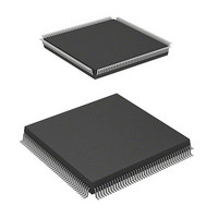
Package / Case
168-QFP
Lead Free Status / RoHS Status
Lead free / RoHS Compliant
Eeprom Size
-
Available stocks
Company
Part Number
Manufacturer
Quantity
Price
Company:

Part Number:
HD64F7051SFJ20V
Manufacturer:
RENESAS
Quantity:
101
Part Number:
HD64F7051SFJ20V
Manufacturer:
RENESAS/瑞萨
Quantity:
20 000


Section 20 RAM
20.1 Overview........................................................................................................................... 639
20.2 Operation .......................................................................................................................... 640
Section 21 Power-Down State
21.1 Overview........................................................................................................................... 641
21.2 Register Descriptions ........................................................................................................ 644
21.3 Hardware Standby Mode .................................................................................................. 646
21.4 Software Standby Mode.................................................................................................... 647
21.5 Sleep Mode ....................................................................................................................... 651
Section 22 Electrical Characteristics
22.1 Absolute Maximum Ratings ............................................................................................. 653
22.2 DC Characteristics ............................................................................................................ 654
22.3 AC Characteristics ............................................................................................................ 657
22.4 A/D Converter Characteristics .......................................................................................... 674
21.1.1 Power-Down States.............................................................................................. 641
21.1.2 Pin Configuration................................................................................................. 643
21.1.3 Related Register ................................................................................................... 643
21.2.1 Standby Control Register (SBYCR) .................................................................... 644
21.2.2 System Control Register (SYSCR) ...................................................................... 645
21.3.1 Transition to Hardware Standby Mode ................................................................ 646
21.3.2 Exit from Hardware Standby Mode ..................................................................... 646
21.3.3 Hardware Standby Mode Timing......................................................................... 646
21.4.1 Transition to Software Standby Mode ................................................................. 647
21.4.2 Canceling the Software Standby Mode................................................................ 649
21.4.3 Software Standby Mode Application Example.................................................... 650
21.5.1 Transition to Sleep Mode..................................................................................... 651
21.5.2 Canceling Sleep Mode ......................................................................................... 651
22.2.1 Notes on Using..................................................................................................... 656
22.3.1 Clock Timing ....................................................................................................... 657
22.3.2 Control Signal Timing ......................................................................................... 659
22.3.3 Bus Timing .......................................................................................................... 662
22.3.4 Direct Memory Access Controller Timing .......................................................... 666
22.3.5 Advanced Timer Unit Timing and Advanced Pulse Controller Timing .............. 668
22.3.6 I/O Port Timing.................................................................................................... 669
22.3.7 Watchdog Timer Timing...................................................................................... 670
22.3.8 Serial Communication Interface Timing.............................................................. 670
22.3.9 A/D Converter Timing......................................................................................... 671
22.3.10 Measuring Conditions for AC Characteristics ..................................................... 673
.................................................................................................................. 639
......................................................................................... 641
.............................................................................. 653
Rev. 5.00 Jan 06, 2006 page xix of xx
Related parts for HD64F7051SFJ20V
Image
Part Number
Description
Manufacturer
Datasheet
Request
R

Part Number:
Description:
KIT STARTER FOR M16C/29
Manufacturer:
Renesas Electronics America
Datasheet:

Part Number:
Description:
KIT STARTER FOR R8C/2D
Manufacturer:
Renesas Electronics America
Datasheet:

Part Number:
Description:
R0K33062P STARTER KIT
Manufacturer:
Renesas Electronics America
Datasheet:

Part Number:
Description:
KIT STARTER FOR R8C/23 E8A
Manufacturer:
Renesas Electronics America
Datasheet:

Part Number:
Description:
KIT STARTER FOR R8C/25
Manufacturer:
Renesas Electronics America
Datasheet:

Part Number:
Description:
KIT STARTER H8S2456 SHARPE DSPLY
Manufacturer:
Renesas Electronics America
Datasheet:

Part Number:
Description:
KIT STARTER FOR R8C38C
Manufacturer:
Renesas Electronics America
Datasheet:

Part Number:
Description:
KIT STARTER FOR R8C35C
Manufacturer:
Renesas Electronics America
Datasheet:

Part Number:
Description:
KIT STARTER FOR R8CL3AC+LCD APPS
Manufacturer:
Renesas Electronics America
Datasheet:
Part Number:
Description:
KIT STARTER FOR RX610
Manufacturer:
Renesas Electronics America
Datasheet:

Part Number:
Description:
KIT STARTER FOR R32C/118
Manufacturer:
Renesas Electronics America
Datasheet:

Part Number:
Description:
KIT DEV RSK-R8C/26-29
Manufacturer:
Renesas Electronics America
Datasheet:

Part Number:
Description:
KIT STARTER FOR SH7124
Manufacturer:
Renesas Electronics America
Datasheet:

Part Number:
Description:
KIT STARTER FOR H8SX/1622
Manufacturer:
Renesas Electronics America
Datasheet:

Part Number:
Description:
KIT DEV FOR SH7203
Manufacturer:
Renesas Electronics America
Datasheet: