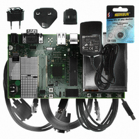
AT91SAM9G10-EK Atmel, AT91SAM9G10-EK Datasheet - Page 713

AT91SAM9G10-EK
Manufacturer Part Number
AT91SAM9G10-EK
Description
KIT DEV FOR SAM9G10 ARM
Manufacturer
Atmel
Type
MCUr
Specifications of AT91SAM9G10-EK
Contents
Board, Cables, Power Supply
Silicon Manufacturer
Atmel
Core Architecture
AVR
Kit Contents
Board
Svhc
No SVHC (15-Dec-2010)
Mcu Supported Families
AT91SAM9G10, ARM926EJ-S
Tool / Board Applications
Microcontroller
Rohs Compliant
Yes
For Use With/related Products
*
Lead Free Status / RoHS Status
Contains lead / RoHS non-compliant
- Current page: 713 of 730
- Download datasheet (12Mb)
42.2.4
42.2.4.1
42.2.4.2
42.2.5
42.2.5.1
42.2.6
42.2.6.1
6462A–ATARM–03-Jun-09
MCI
NTRST
Serial Peripheral Interface (SPI)
MCI: Busy Signal of R1b Responses Is Not Taken In Account
MCI: Data Timeout Error Flag
NTRST: Device Does Not Boot Correctly due to Power-up Sequencing Issue
SPI: Baudrate Set to 1
Powering LCD off, then powering LCD on, resets the FIFO pointers.
Disabling DMA, then enabling DMA, resets the DMA pointers.
The busy status of the card during the response (R1b) is ignored for the commands CMD7,
CMD28, CMD29, CMD38, CMD42, CMD56. Additionally, for commands CMD42 and CMD56 a
conflict can occur on data line 0 if the MCI sends data to the card while the card is still busy.
The behavior is correct for CMD12 command (STOP_TRANSFER).
None
As the data timeout error flag cannot rise, the MCI is stalled indefinitely waiting for the data start
bit.
A STOP command must be sent with a software timeout.
The NTRST signal is powered by VDDIOP power supply (3.3V) and the ARM processor is pow-
ered by VDDCORE power supply (1.2V).
During the power-up sequence, if VDDIOP power supply is not established whereas the
VDDCORE Power On Reset output is released, the NTRST signal is not correctly asserted. The
ARM processor then enters debug state and the device does not boot correctly.
When Baudrate is set at 1 (i.e. when serial clock frequency equals the system clock frequency),
and when the fields BITS (number of bits to be transmitted) equals an ODD value (in this case
9,11,13 or 15), an additional pulse is generated on output SPCK. No problem occurs if BITS field
equals 8,10,12,14 or 16 and Baudrate = 1.
• LCD power off
• DMA disable
• Wait for DMABUSY
• DMA reset
• LCD power on
• DMA enable.
1. Connect NTRST pin to NRST pin to ensure that a correct powering sequence takes
2. Connect NTRST to GND if no debug capabilities are required.
Problem Fix/Workaround
Problem Fix/Workaround
Problem Fix/Workaround
place in all cases.
AT91SAM9G10
713
Related parts for AT91SAM9G10-EK
Image
Part Number
Description
Manufacturer
Datasheet
Request
R

Part Number:
Description:
MCU, MPU & DSP Development Tools KICKSTART KIT FOR AT91SAM9 PLUS
Manufacturer:
IAR Systems

Part Number:
Description:
DEV KIT FOR AVR/AVR32
Manufacturer:
Atmel
Datasheet:

Part Number:
Description:
INTERVAL AND WIPE/WASH WIPER CONTROL IC WITH DELAY
Manufacturer:
ATMEL Corporation
Datasheet:

Part Number:
Description:
Low-Voltage Voice-Switched IC for Hands-Free Operation
Manufacturer:
ATMEL Corporation
Datasheet:

Part Number:
Description:
MONOLITHIC INTEGRATED FEATUREPHONE CIRCUIT
Manufacturer:
ATMEL Corporation
Datasheet:

Part Number:
Description:
AM-FM Receiver IC U4255BM-M
Manufacturer:
ATMEL Corporation
Datasheet:

Part Number:
Description:
Monolithic Integrated Feature Phone Circuit
Manufacturer:
ATMEL Corporation
Datasheet:

Part Number:
Description:
Multistandard Video-IF and Quasi Parallel Sound Processing
Manufacturer:
ATMEL Corporation
Datasheet:

Part Number:
Description:
High-performance EE PLD
Manufacturer:
ATMEL Corporation
Datasheet:

Part Number:
Description:
8-bit Flash Microcontroller
Manufacturer:
ATMEL Corporation
Datasheet:

Part Number:
Description:
2-Wire Serial EEPROM
Manufacturer:
ATMEL Corporation
Datasheet:


