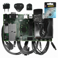
AT91SAM9G10-EK Atmel, AT91SAM9G10-EK Datasheet - Page 238

AT91SAM9G10-EK
Manufacturer Part Number
AT91SAM9G10-EK
Description
KIT DEV FOR SAM9G10 ARM
Manufacturer
Atmel
Type
MCUr
Specifications of AT91SAM9G10-EK
Contents
Board, Cables, Power Supply
Silicon Manufacturer
Atmel
Core Architecture
AVR
Kit Contents
Board
Svhc
No SVHC (15-Dec-2010)
Mcu Supported Families
AT91SAM9G10, ARM926EJ-S
Tool / Board Applications
Microcontroller
Rohs Compliant
Yes
For Use With/related Products
*
Lead Free Status / RoHS Status
Contains lead / RoHS non-compliant
- Current page: 238 of 730
- Download datasheet (12Mb)
Figure 25-2. Main Oscillator Block Diagram
25.3.1
Figure 25-3. Typical Crystal Connection
25.3.2
25.3.3
238
AT91SAM9G10
Main Oscillator Connections
Main Oscillator Startup Time
Main Oscillator Control
The Clock Generator integrates a Main Oscillator that is designed for a
crystal. The typical crystal connection is illustrated in
required for crystals with frequencies lower than 8 MHz. For further details on the electrical char-
acteristics of the Main Oscillator, see the section “DC Characteristics” of the product datasheet.
The startup time of the Main Oscillator is given in the DC Characteristics section of the product
datasheet. The startup time depends on the crystal frequency and decreases when the fre-
quency rises.
To minimize the power required to start up the system, the main oscillator is disabled after reset
and slow clock is selected.
The software enables or disables the main oscillator so as to reduce power consumption by
clearing the MOSCEN bit in the Main Oscillator Register (CKGR_MOR).
Slow Clock
XOUT
SLCK
XIN
XIN
Main Clock
OSCOUNT
Frequency
Oscillator
MOSCEN
Oscillator
XOUT
Counter
Counter
Main
Main
GND
Main Clock
MAINCK
MAINRDY
MOSCS
MAINF
Figure
25-3. The 1 k
3 to 20
6462A–ATARM–03-Jun-09
Ω
MHz fundamental
resistor is only
Related parts for AT91SAM9G10-EK
Image
Part Number
Description
Manufacturer
Datasheet
Request
R

Part Number:
Description:
MCU, MPU & DSP Development Tools KICKSTART KIT FOR AT91SAM9 PLUS
Manufacturer:
IAR Systems

Part Number:
Description:
DEV KIT FOR AVR/AVR32
Manufacturer:
Atmel
Datasheet:

Part Number:
Description:
INTERVAL AND WIPE/WASH WIPER CONTROL IC WITH DELAY
Manufacturer:
ATMEL Corporation
Datasheet:

Part Number:
Description:
Low-Voltage Voice-Switched IC for Hands-Free Operation
Manufacturer:
ATMEL Corporation
Datasheet:

Part Number:
Description:
MONOLITHIC INTEGRATED FEATUREPHONE CIRCUIT
Manufacturer:
ATMEL Corporation
Datasheet:

Part Number:
Description:
AM-FM Receiver IC U4255BM-M
Manufacturer:
ATMEL Corporation
Datasheet:

Part Number:
Description:
Monolithic Integrated Feature Phone Circuit
Manufacturer:
ATMEL Corporation
Datasheet:

Part Number:
Description:
Multistandard Video-IF and Quasi Parallel Sound Processing
Manufacturer:
ATMEL Corporation
Datasheet:

Part Number:
Description:
High-performance EE PLD
Manufacturer:
ATMEL Corporation
Datasheet:

Part Number:
Description:
8-bit Flash Microcontroller
Manufacturer:
ATMEL Corporation
Datasheet:

Part Number:
Description:
2-Wire Serial EEPROM
Manufacturer:
ATMEL Corporation
Datasheet:


