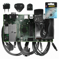
AT91SAM9G10-EK Atmel, AT91SAM9G10-EK Datasheet - Page 593

AT91SAM9G10-EK
Manufacturer Part Number
AT91SAM9G10-EK
Description
KIT DEV FOR SAM9G10 ARM
Manufacturer
Atmel
Type
MCUr
Specifications of AT91SAM9G10-EK
Contents
Board, Cables, Power Supply
Silicon Manufacturer
Atmel
Core Architecture
AVR
Kit Contents
Board
Svhc
No SVHC (15-Dec-2010)
Mcu Supported Families
AT91SAM9G10, ARM926EJ-S
Tool / Board Applications
Microcontroller
Rohs Compliant
Yes
For Use With/related Products
*
Lead Free Status / RoHS Status
Contains lead / RoHS non-compliant
- Current page: 593 of 730
- Download datasheet (12Mb)
37.3.2
37.3.3
593
AT91SAM9G10
Power Management
Interrupt
To reserve an I/O line to check VBUS, the programmer must first program the PIO controller to
assign this I/O in input PIO mode.
The USB device peripheral requires a 48 MHz clock. This clock must be generated by a PLL
with an accuracy of ± 0.25%.
Thus, the USB device receives two clocks from the Power Management Controller (PMC): the
master clock, MCK, used to drive the peripheral user interface, and the UDPCK, used to inter-
face with the bus USB signals (recovered 12 MHz domain).
WARNING: The UDP peripheral clock in the Power Management Controller (PMC) must be
enabled before any read/write operations to the UDP registers including the UDP_TXVC
register.
The USB device interface has an interrupt line connected to the Advanced Interrupt Controller
(AIC).
Handling the USB device interrupt requires programming the AIC before configuring the UDP.
Table 37-2.
Instance
UDP
Peripheral IDs
10
ID
6462A–ATARM–03-Jun-09
Related parts for AT91SAM9G10-EK
Image
Part Number
Description
Manufacturer
Datasheet
Request
R

Part Number:
Description:
MCU, MPU & DSP Development Tools KICKSTART KIT FOR AT91SAM9 PLUS
Manufacturer:
IAR Systems

Part Number:
Description:
DEV KIT FOR AVR/AVR32
Manufacturer:
Atmel
Datasheet:

Part Number:
Description:
INTERVAL AND WIPE/WASH WIPER CONTROL IC WITH DELAY
Manufacturer:
ATMEL Corporation
Datasheet:

Part Number:
Description:
Low-Voltage Voice-Switched IC for Hands-Free Operation
Manufacturer:
ATMEL Corporation
Datasheet:

Part Number:
Description:
MONOLITHIC INTEGRATED FEATUREPHONE CIRCUIT
Manufacturer:
ATMEL Corporation
Datasheet:

Part Number:
Description:
AM-FM Receiver IC U4255BM-M
Manufacturer:
ATMEL Corporation
Datasheet:

Part Number:
Description:
Monolithic Integrated Feature Phone Circuit
Manufacturer:
ATMEL Corporation
Datasheet:

Part Number:
Description:
Multistandard Video-IF and Quasi Parallel Sound Processing
Manufacturer:
ATMEL Corporation
Datasheet:

Part Number:
Description:
High-performance EE PLD
Manufacturer:
ATMEL Corporation
Datasheet:

Part Number:
Description:
8-bit Flash Microcontroller
Manufacturer:
ATMEL Corporation
Datasheet:

Part Number:
Description:
2-Wire Serial EEPROM
Manufacturer:
ATMEL Corporation
Datasheet:


