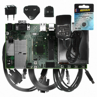
AT91SAM9G10-EK Atmel, AT91SAM9G10-EK Datasheet - Page 201

AT91SAM9G10-EK
Manufacturer Part Number
AT91SAM9G10-EK
Description
KIT DEV FOR SAM9G10 ARM
Manufacturer
Atmel
Type
MCUr
Specifications of AT91SAM9G10-EK
Contents
Board, Cables, Power Supply
Silicon Manufacturer
Atmel
Core Architecture
AVR
Kit Contents
Board
Svhc
No SVHC (15-Dec-2010)
Mcu Supported Families
AT91SAM9G10, ARM926EJ-S
Tool / Board Applications
Microcontroller
Rohs Compliant
Yes
For Use With/related Products
*
Lead Free Status / RoHS Status
Contains lead / RoHS non-compliant
- Current page: 201 of 730
- Download datasheet (12Mb)
23. SDRAM Controller (SDRAMC)
23.1
23.2
6462A–ATARM–03-Jun-09
Description
I/O Lines Description
The SDRAM Controller (SDRAMC) extends the memory capabilities of a chip by providing the
interface to an external 16-bit or 32-bit SDRAM device. The page size supports ranges from
2048 to 8192 and the number of columns from 256 to 2048. It supports byte (8-bit), half-word
(16-bit) and word (32-bit) accesses.
The SDRAM Controller supports a read or write burst length of one location. It keeps track of the
active row in each bank, thus maximizing SDRAM performance, e.g., the application may be
placed in one bank and data in the other banks. So as to optimize performance, it is advisable to
avoid accessing different rows in the same bank.
The SDRAM controller supports a CAS latency of 1, 2 or 3 and optimizes the read access
depending on the frequency.
The different modes available - self-refresh, power-down and deep power-down modes - mini-
mize power consumption on the SDRAM device.
Table 23-1.
Name
SDCK
SDCKE
SDCS
BA[1:0]
RAS
CAS
SDWE
NBS[3:0]
SDRAMC_A[12:0]
D[31:0]
I/O Line Description
SDRAM Clock
SDRAM Clock Enable
SDRAM Controller Chip Select
Bank Select Signals
Column Signal
SDRAM Write Enable
Data Mask Enable Signals
Address Bus
Data Bus
Description
Row Signal
Output
Output
Output
Output
Output
Output
Output
Output
Output
Type
AT91SAM9G10
I/O
Active Level
High
Low
Low
Low
Low
Low
201
Related parts for AT91SAM9G10-EK
Image
Part Number
Description
Manufacturer
Datasheet
Request
R

Part Number:
Description:
MCU, MPU & DSP Development Tools KICKSTART KIT FOR AT91SAM9 PLUS
Manufacturer:
IAR Systems

Part Number:
Description:
DEV KIT FOR AVR/AVR32
Manufacturer:
Atmel
Datasheet:

Part Number:
Description:
INTERVAL AND WIPE/WASH WIPER CONTROL IC WITH DELAY
Manufacturer:
ATMEL Corporation
Datasheet:

Part Number:
Description:
Low-Voltage Voice-Switched IC for Hands-Free Operation
Manufacturer:
ATMEL Corporation
Datasheet:

Part Number:
Description:
MONOLITHIC INTEGRATED FEATUREPHONE CIRCUIT
Manufacturer:
ATMEL Corporation
Datasheet:

Part Number:
Description:
AM-FM Receiver IC U4255BM-M
Manufacturer:
ATMEL Corporation
Datasheet:

Part Number:
Description:
Monolithic Integrated Feature Phone Circuit
Manufacturer:
ATMEL Corporation
Datasheet:

Part Number:
Description:
Multistandard Video-IF and Quasi Parallel Sound Processing
Manufacturer:
ATMEL Corporation
Datasheet:

Part Number:
Description:
High-performance EE PLD
Manufacturer:
ATMEL Corporation
Datasheet:

Part Number:
Description:
8-bit Flash Microcontroller
Manufacturer:
ATMEL Corporation
Datasheet:

Part Number:
Description:
2-Wire Serial EEPROM
Manufacturer:
ATMEL Corporation
Datasheet:


