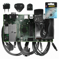
AT91SAM9G10-EK Atmel, AT91SAM9G10-EK Datasheet - Page 712

AT91SAM9G10-EK
Manufacturer Part Number
AT91SAM9G10-EK
Description
KIT DEV FOR SAM9G10 ARM
Manufacturer
Atmel
Type
MCUr
Specifications of AT91SAM9G10-EK
Contents
Board, Cables, Power Supply
Silicon Manufacturer
Atmel
Core Architecture
AVR
Kit Contents
Board
Svhc
No SVHC (15-Dec-2010)
Mcu Supported Families
AT91SAM9G10, ARM926EJ-S
Tool / Board Applications
Microcontroller
Rohs Compliant
Yes
For Use With/related Products
*
Lead Free Status / RoHS Status
Contains lead / RoHS non-compliant
- Current page: 712 of 730
- Download datasheet (12Mb)
42.2
42.2.1
42.2.1.1
42.2.2
42.2.2.1
42.2.3
42.2.3.1
712
AT91SAM9G10 Errata - Revision A Parts
AT91SAM9G10
Battery Backup
Bus Matrix
LCD
Backup Overconsumption During AHB Masters Activity
Bus Matrix: Problem with Locked Transfers
LCD: Screen Shifting After a Reset
Refer to
Conditions:
During AHB Masters activity (LCD DMA, USB Host DMA, etc.) the backup current can rise up to
12 µA @ 25⋅ C.
Figure 42-1 on page 712
when the main power supply is off. In active mode, the clocks of unused peripherals should be
disabled through the Power Management Controller to save power.
Figure 42-1. Schematic
Locked transfers are not correctly handled by the Bus Matrix and can lead to a system freeze
up. This does not concern ARM locked transfers.
Avoid other Bus Matrix masters locked transfers.
When a FIFO underflow occurs, a reset of the LCD DMA and FIFO pointers is necessary.
If only LCD DMA pointers are reset (FIFO pointers not reset), the displayed image is shifted.
Apply the following sequence to correctly reset LCD DMA and FIFO pointers:
Problem Fix/Workaround
Problem Fix/Workaround
Problem Fix/Workaround
Section 42.1 “Marking” on page
J1
CR1225
Z1
+
3V
shows how to feed the backup part of the chip from the battery only
MMBD1704A
R1
CR1
1K
711.
3V3
3
C1
100NF
MN1
R1100D121C
C2
100NF
VDDBU
6462A–ATARM–03-Jun-09
Related parts for AT91SAM9G10-EK
Image
Part Number
Description
Manufacturer
Datasheet
Request
R

Part Number:
Description:
MCU, MPU & DSP Development Tools KICKSTART KIT FOR AT91SAM9 PLUS
Manufacturer:
IAR Systems

Part Number:
Description:
DEV KIT FOR AVR/AVR32
Manufacturer:
Atmel
Datasheet:

Part Number:
Description:
INTERVAL AND WIPE/WASH WIPER CONTROL IC WITH DELAY
Manufacturer:
ATMEL Corporation
Datasheet:

Part Number:
Description:
Low-Voltage Voice-Switched IC for Hands-Free Operation
Manufacturer:
ATMEL Corporation
Datasheet:

Part Number:
Description:
MONOLITHIC INTEGRATED FEATUREPHONE CIRCUIT
Manufacturer:
ATMEL Corporation
Datasheet:

Part Number:
Description:
AM-FM Receiver IC U4255BM-M
Manufacturer:
ATMEL Corporation
Datasheet:

Part Number:
Description:
Monolithic Integrated Feature Phone Circuit
Manufacturer:
ATMEL Corporation
Datasheet:

Part Number:
Description:
Multistandard Video-IF and Quasi Parallel Sound Processing
Manufacturer:
ATMEL Corporation
Datasheet:

Part Number:
Description:
High-performance EE PLD
Manufacturer:
ATMEL Corporation
Datasheet:

Part Number:
Description:
8-bit Flash Microcontroller
Manufacturer:
ATMEL Corporation
Datasheet:

Part Number:
Description:
2-Wire Serial EEPROM
Manufacturer:
ATMEL Corporation
Datasheet:


