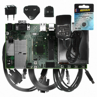
AT91SAM9G10-EK Atmel, AT91SAM9G10-EK Datasheet - Page 554

AT91SAM9G10-EK
Manufacturer Part Number
AT91SAM9G10-EK
Description
KIT DEV FOR SAM9G10 ARM
Manufacturer
Atmel
Type
MCUr
Specifications of AT91SAM9G10-EK
Contents
Board, Cables, Power Supply
Silicon Manufacturer
Atmel
Core Architecture
AVR
Kit Contents
Board
Svhc
No SVHC (15-Dec-2010)
Mcu Supported Families
AT91SAM9G10, ARM926EJ-S
Tool / Board Applications
Microcontroller
Rohs Compliant
Yes
For Use With/related Products
*
Lead Free Status / RoHS Status
Contains lead / RoHS non-compliant
- Current page: 554 of 730
- Download datasheet (12Mb)
Figure 35-6. SD Card Bus Connections with One Slot
Note:
35.7
6462A–ATARM–03-Jun-09
When several MCI (x MCI) are embedded in a product, MCCK refers to MCIx_CK, MCCDA to MCIx_CDA MCDAy to MCIx_DAy.
MultiMedia Card Operations
Table 35-5.
Notes:
When the MCI is configured to operate with SD memory cards, the width of the data bus can be
selected in the MCI_SDCR register. Clearing the SDCBUS bit in this register means that the
width is one bit; setting it means that the width is four bits. In the case of multimedia cards, only
the data line 0 is used. The other data lines can be used as independent PIOs.
After a power-on reset, the cards are initialized by a special message-based MultiMedia Card
bus protocol. Each message is represented by one of the following tokens:
Card addressing is implemented using a session address assigned during the initialization
phase by the bus controller to all currently connected cards. Their unique CID number identifies
individual cards.
The structure of commands, responses and data blocks is described in the MultiMedia-Card
System Specification. See also
MultiMediaCard bus data transfers are composed of these tokens.
There are different types of operations. Addressed operations always contain a command and a
response token. In addition, some operations have a data token; the others transfer their infor-
mation directly within the command or response structure. In this case, no data token is present
Pin Number
7
8
9
• Command: A command is a token that starts an operation. A command is sent from the host
• Response: A response is a token which is sent from an addressed card or (synchronously)
• Data: Data can be transferred from the card to the host or vice versa. Data is transferred via
either to a single card (addressed command) or to all connected cards (broadcast
command). A command is transferred serially on the CMD line.
from all connected cards to the host as an answer to a previously received command. A
response is transferred serially on the CMD line.
the data line.
1. I: input, O: output, PP: Push Pull, OD: Open Drain.
2. When several MCI (x MCI) are embedded in a product, MCCK refers to MCIx_CK, MCCDA to
MCDA0 - MCDA3
MCIx_CDA, MCDAy to MCIx_DAy.
SD Memory Card Bus Signals
Name
DAT[0]
DAT[1]
DAT[2]
MCCDA
MCCK
Type
I/O/PP
I/O/PP
I/O/PP
Table 35-6 on page
(1)
Description
Data line Bit 0
Data line Bit 1 or Interrupt
Data line Bit 2
555.
SD CARD
AT91SAM9G10
MCI Pin Name
(Slot z)
MCDz0
MCDz1
MCDz2
(2)
554
Related parts for AT91SAM9G10-EK
Image
Part Number
Description
Manufacturer
Datasheet
Request
R

Part Number:
Description:
MCU, MPU & DSP Development Tools KICKSTART KIT FOR AT91SAM9 PLUS
Manufacturer:
IAR Systems

Part Number:
Description:
DEV KIT FOR AVR/AVR32
Manufacturer:
Atmel
Datasheet:

Part Number:
Description:
INTERVAL AND WIPE/WASH WIPER CONTROL IC WITH DELAY
Manufacturer:
ATMEL Corporation
Datasheet:

Part Number:
Description:
Low-Voltage Voice-Switched IC for Hands-Free Operation
Manufacturer:
ATMEL Corporation
Datasheet:

Part Number:
Description:
MONOLITHIC INTEGRATED FEATUREPHONE CIRCUIT
Manufacturer:
ATMEL Corporation
Datasheet:

Part Number:
Description:
AM-FM Receiver IC U4255BM-M
Manufacturer:
ATMEL Corporation
Datasheet:

Part Number:
Description:
Monolithic Integrated Feature Phone Circuit
Manufacturer:
ATMEL Corporation
Datasheet:

Part Number:
Description:
Multistandard Video-IF and Quasi Parallel Sound Processing
Manufacturer:
ATMEL Corporation
Datasheet:

Part Number:
Description:
High-performance EE PLD
Manufacturer:
ATMEL Corporation
Datasheet:

Part Number:
Description:
8-bit Flash Microcontroller
Manufacturer:
ATMEL Corporation
Datasheet:

Part Number:
Description:
2-Wire Serial EEPROM
Manufacturer:
ATMEL Corporation
Datasheet:


