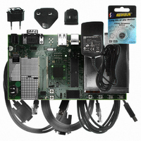
AT91SAM9G10-EK Atmel, AT91SAM9G10-EK Datasheet - Page 141

AT91SAM9G10-EK
Manufacturer Part Number
AT91SAM9G10-EK
Description
KIT DEV FOR SAM9G10 ARM
Manufacturer
Atmel
Type
MCUr
Specifications of AT91SAM9G10-EK
Contents
Board, Cables, Power Supply
Silicon Manufacturer
Atmel
Core Architecture
AVR
Kit Contents
Board
Svhc
No SVHC (15-Dec-2010)
Mcu Supported Families
AT91SAM9G10, ARM926EJ-S
Tool / Board Applications
Microcontroller
Rohs Compliant
Yes
For Use With/related Products
*
Lead Free Status / RoHS Status
Contains lead / RoHS non-compliant
- Current page: 141 of 730
- Download datasheet (12Mb)
21.4.2
Figure 21-2. EBI Connections to Memory Devices
21.5
21.5.1
6462A–ATARM–03-Jun-09
Product Dependencies
Connection Examples
I/O Lines
EBI
A1/NWR2/NBS2
NWR1/NBS1
NWR3/NBS3
NWR0/NWE
NCS1/SDCS
Figure 21-2
The pins used for interfacing the External Bus Interface may be multiplexed with the PIO lines.
The programmer must first program the PIO controller to assign the External Bus Interface pins
to their peripheral function. If I/O lines of the External Bus Interface are not used by the applica-
tion, they can be used for other purposes by the PIO Controller.
A0/NBS0
A16/BA0
A17/BA1
A18-A25
D0-D31
A2-A15
SDCKE
SDA10
SDCK
SDWE
NCS2
NCS3
NCS4
NCS5
NCS6
NCS7
NCS0
NRD
RAS
CAS
shows an example of connections between the EBI and external devices.
A0/NWR0/NBS0
NRD/NOE
D0-D7
D16-D23
D0-D7
NBS0
SDWE
SDWE
NBS2
D0-D7
CS
CLK
CKE
WE
RAS
CAS
DQM
D0-D7
CS
CLK
CKE
WE
RAS
CAS
DQM
D0-D7
CS
OE
WE
128K x 8
SRAM
SDRAM
SDRAM
2M x 8
2M x 8
A0-A9, A11
A0-A9, A11
A0-A16
BA0
BA1
A10
BA0
BA1
A10
A2-A11, A13
SDA10
A16/BA0
A17/BA1
A2-A11, A13
SDA10
A16/BA0
A17/BA1
A1-A17
D8-D15
NWR1/NBS1
NRD/NOE
D24-D31
D8-D15
SDWE
SDWE
NBS3
NBS1
D0-D7
CS
OE
WE
128K x 8
CS
CLK
CKE
WE
RAS
CAS
DQM
D0-D7
CS
CLK
CKE
WE
RAS
CAS
DQM
D0-D7
SRAM
SDRAM
2M x 8
SDRAM
2M x 8
A0-A16
A0-A9, A11
A0-A9, A11
BA0
BA1
A10
BA0
BA1
A10
A2-A11, A13
SDA10
A16/BA0
A17/BA1
A1-A17
A2-A11, A13
SDA10
A16/BA0
A17/BA1
AT91SAM9G10
141
Related parts for AT91SAM9G10-EK
Image
Part Number
Description
Manufacturer
Datasheet
Request
R

Part Number:
Description:
MCU, MPU & DSP Development Tools KICKSTART KIT FOR AT91SAM9 PLUS
Manufacturer:
IAR Systems

Part Number:
Description:
DEV KIT FOR AVR/AVR32
Manufacturer:
Atmel
Datasheet:

Part Number:
Description:
INTERVAL AND WIPE/WASH WIPER CONTROL IC WITH DELAY
Manufacturer:
ATMEL Corporation
Datasheet:

Part Number:
Description:
Low-Voltage Voice-Switched IC for Hands-Free Operation
Manufacturer:
ATMEL Corporation
Datasheet:

Part Number:
Description:
MONOLITHIC INTEGRATED FEATUREPHONE CIRCUIT
Manufacturer:
ATMEL Corporation
Datasheet:

Part Number:
Description:
AM-FM Receiver IC U4255BM-M
Manufacturer:
ATMEL Corporation
Datasheet:

Part Number:
Description:
Monolithic Integrated Feature Phone Circuit
Manufacturer:
ATMEL Corporation
Datasheet:

Part Number:
Description:
Multistandard Video-IF and Quasi Parallel Sound Processing
Manufacturer:
ATMEL Corporation
Datasheet:

Part Number:
Description:
High-performance EE PLD
Manufacturer:
ATMEL Corporation
Datasheet:

Part Number:
Description:
8-bit Flash Microcontroller
Manufacturer:
ATMEL Corporation
Datasheet:

Part Number:
Description:
2-Wire Serial EEPROM
Manufacturer:
ATMEL Corporation
Datasheet:


