HD6417709SF133B Renesas Electronics America, HD6417709SF133B Datasheet - Page 266
HD6417709SF133B
Manufacturer Part Number
HD6417709SF133B
Description
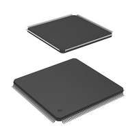
IC SUPERH MPU ROMLESS 208LQFP
Manufacturer
Renesas Electronics America
Series
SuperH® SH7700r
Datasheet
1.D6417709SBP167BV.pdf
(809 pages)
Specifications of HD6417709SF133B
Core Processor
SH-3
Core Size
32-Bit
Speed
133MHz
Connectivity
EBI/EMI, FIFO, IrDA, SCI, SmartCard
Peripherals
DMA, POR, WDT
Number Of I /o
96
Program Memory Type
ROMless
Ram Size
16K x 8
Voltage - Supply (vcc/vdd)
1.65 V ~ 2.05 V
Data Converters
A/D 8x10b; D/A 2x8b
Oscillator Type
Internal
Operating Temperature
-20°C ~ 75°C
Package / Case
208-LQFP
Lead Free Status / RoHS Status
Contains lead / RoHS non-compliant
Eeprom Size
-
Program Memory Size
-
Available stocks
Company
Part Number
Manufacturer
Quantity
Price
Company:

Part Number:
HD6417709SF133B
Manufacturer:
RENESAS
Quantity:
79
Company:
Part Number:
HD6417709SF133B
Manufacturer:
Renesas Electronics America
Quantity:
10 000
Part Number:
HD6417709SF133B
Manufacturer:
RENESAS/瑞萨
Quantity:
20 000
Part Number:
HD6417709SF133B-V
Manufacturer:
RENESAS/瑞萨
Quantity:
20 000
Part Number:
HD6417709SF133BV
Manufacturer:
RENESAS/瑞萨
Quantity:
20 000


9.9
When Using an External Crystal Resonator: Place the crystal resonator, capacitors CL1 and
CL2 close to the EXTAL and XTAL pins. To prevent induction from interfering with correct
oscillation, use a common grounding point for the capacitors connected to the resonator, and do
not locate a wiring pattern near these components.
Decoupling Capacitors: Insert a laminated ceramic capacitor of 0.1 to 1 F as a passive capacitor
for each V
use components with a frequency characteristic suitable for the chip’s operating frequency, as well
as a suitable capacitance value.
Digital system V
111, 132-134, 153-154, 161-163, 173-175, 181-183, 205-208
On-chip oscillator V
Note: The pin numbers above apply to LQFP and HQFP packages.
When Using a PLL Oscillator Circuit: Keep the wiring from the PLL V
pattern to the power supply pins short, and make the pattern width large, to minimize the
inductance component. Ground the oscillation stabilization capacitors C1 and C2 to V
and V
locate a wiring pattern in the vicinity. In clock mode 7, connect the EXTAL pin to V
leave the XTAL pin open.
Rev. 5.00, 09/03, page 220 of 760
SS
(PLL2), respectively. Place C1 and C2 close to the CAP1 and CAP2 pins and do not
Notes on Board Design
SS
/V
CC
Figure 9.4 Points for Attention when Using Crystal Resonator
SS
pair. Mount the passive capacitors close to the SH7709S power supply pins, and
Note: The values for CL1 and CL2 should be determined after
/V
SS
CC
/V
pairs: 19-21, 27-29, 33-35, 45-47, 57-59, 69-71, 79-81, 83-85, 95-97, 109-
CC
consultation with the crystal manufacturer.
pairs: 3-6, 145-147, 148-150
EXTAL
Avoid crossing
signal lines
CL1
SH7709S
XTAL
CL2
CC
and V
SS
CC
connection
SS
or V
(PLL1)
SS
and
Related parts for HD6417709SF133B
Image
Part Number
Description
Manufacturer
Datasheet
Request
R

Part Number:
Description:
KIT STARTER FOR M16C/29
Manufacturer:
Renesas Electronics America
Datasheet:

Part Number:
Description:
KIT STARTER FOR R8C/2D
Manufacturer:
Renesas Electronics America
Datasheet:

Part Number:
Description:
R0K33062P STARTER KIT
Manufacturer:
Renesas Electronics America
Datasheet:

Part Number:
Description:
KIT STARTER FOR R8C/23 E8A
Manufacturer:
Renesas Electronics America
Datasheet:

Part Number:
Description:
KIT STARTER FOR R8C/25
Manufacturer:
Renesas Electronics America
Datasheet:

Part Number:
Description:
KIT STARTER H8S2456 SHARPE DSPLY
Manufacturer:
Renesas Electronics America
Datasheet:

Part Number:
Description:
KIT STARTER FOR R8C38C
Manufacturer:
Renesas Electronics America
Datasheet:

Part Number:
Description:
KIT STARTER FOR R8C35C
Manufacturer:
Renesas Electronics America
Datasheet:

Part Number:
Description:
KIT STARTER FOR R8CL3AC+LCD APPS
Manufacturer:
Renesas Electronics America
Datasheet:
Part Number:
Description:
KIT STARTER FOR RX610
Manufacturer:
Renesas Electronics America
Datasheet:

Part Number:
Description:
KIT STARTER FOR R32C/118
Manufacturer:
Renesas Electronics America
Datasheet:

Part Number:
Description:
KIT DEV RSK-R8C/26-29
Manufacturer:
Renesas Electronics America
Datasheet:

Part Number:
Description:
KIT STARTER FOR SH7124
Manufacturer:
Renesas Electronics America
Datasheet:

Part Number:
Description:
KIT STARTER FOR H8SX/1622
Manufacturer:
Renesas Electronics America
Datasheet:

Part Number:
Description:
KIT DEV FOR SH7203
Manufacturer:
Renesas Electronics America
Datasheet: