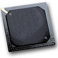
MPC564CZP40 Freescale Semiconductor, MPC564CZP40 Datasheet - Page 95

MPC564CZP40
Manufacturer Part Number
MPC564CZP40
Description
IC MPU 32BIT W/CODE COMP 388PBGA
Manufacturer
Freescale Semiconductor
Series
MPC5xxr
Specifications of MPC564CZP40
Core Processor
PowerPC
Core Size
32-Bit
Speed
40MHz
Connectivity
CAN, EBI/EMI, SCI, SPI, UART/USART
Peripherals
POR, PWM, WDT
Number Of I /o
56
Program Memory Size
512KB (512K x 8)
Program Memory Type
FLASH
Ram Size
32K x 8
Voltage - Supply (vcc/vdd)
2.5 V ~ 2.7 V
Data Converters
A/D 32x10b
Oscillator Type
External
Operating Temperature
-40°C ~ 85°C
Package / Case
388-BGA
Processor Series
MPC5xx
Core
PowerPC
Data Bus Width
32 bit
Data Ram Size
32 KB
Interface Type
CAN, JTAG, QSPI, SCI, SPI, UART
Maximum Clock Frequency
40 MHz
Number Of Programmable I/os
56
Number Of Timers
2
Operating Supply Voltage
0 V to 5 V
Maximum Operating Temperature
+ 85 C
Mounting Style
SMD/SMT
Minimum Operating Temperature
- 40 C
On-chip Adc
2 (10 bit, 32 Channel)
For Use With
MPC564EVB - KIT EVAL FOR MPC561/562/563/564
Lead Free Status / RoHS Status
Contains lead / RoHS non-compliant
Eeprom Size
-
Lead Free Status / Rohs Status
No
Available stocks
Company
Part Number
Manufacturer
Quantity
Price
Company:
Part Number:
MPC564CZP40
Manufacturer:
Freescale Semiconductor
Quantity:
10 000
- Current page: 95 of 1420
- Download datasheet (11Mb)
1.7
The IRAMSTBY pin provides keep-alive power to RAM when the main power supply is shut down. The
IRAMSTBY pin can be powered directly from a battery using an internal shunt regulator or via a small
battery for standby use. See
While power is off, the IRAMSTBY supply powers the following:
1.8
The internal memory map is organized as a single 4-Mbyte block. The user can assign this block to one of
eight locations by programming a register in the USIU (IMMR[ISB]). The eight possible locations are the
Freescale Semiconductor
•
•
•
•
•
•
— READI support
— Reduced data setup time
— Enhanced external burst support
MIOS14
— Four additional PWM channels
— Four additional MCSM timers
DPTRAM (8 Kbytes)
— No functional changes
PPM (peripheral pin multiplexing)
— New module
— Four-to-one multiplexing
— Parallel-to-serial driver (SPI and TDM)
32-Kbyte CALRAM
8-Kbyte DPTRAM module
2-Kbyte BBC DECRAM module
SRAM Keep-Alive Power Behavior
MPC561/MPC563 Address Map
IRAMSTBY must always be supplied with at least 50µA for correct
operation.
Figure 1-2. Recommended Connection Diagram for IRAMSTBY
Figure
MPC561/MPC563 Reference Manual, Rev. 1.2
1-2.
To Battery
R
NOTE
C
To IRAMSTBY Pad
Overview
1-11
Related parts for MPC564CZP40
Image
Part Number
Description
Manufacturer
Datasheet
Request
R

Part Number:
Description:
MPC5 1K0 5%
Manufacturer:
TE Connectivity
Datasheet:

Part Number:
Description:
MPC5 500R 5%
Manufacturer:
TE Connectivity
Datasheet:

Part Number:
Description:
MPC5 5K0 5%
Manufacturer:
Tyco Electronics
Datasheet:

Part Number:
Description:
MPC5 5R0 5%
Manufacturer:
Tyco Electronics
Datasheet:

Part Number:
Description:
MPC5 50K 5%
Manufacturer:
Tyco Electronics
Datasheet:

Part Number:
Description:
MPC5 1R0 5%
Manufacturer:
Tyco Electronics
Datasheet:
Part Number:
Description:
Manufacturer:
Freescale Semiconductor, Inc
Datasheet:
Part Number:
Description:
Manufacturer:
Freescale Semiconductor, Inc
Datasheet:
Part Number:
Description:
Manufacturer:
Freescale Semiconductor, Inc
Datasheet:
Part Number:
Description:
Manufacturer:
Freescale Semiconductor, Inc
Datasheet:
Part Number:
Description:
Manufacturer:
Freescale Semiconductor, Inc
Datasheet:


