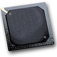
MPC564CZP40 Freescale Semiconductor, MPC564CZP40 Datasheet - Page 284

MPC564CZP40
Manufacturer Part Number
MPC564CZP40
Description
IC MPU 32BIT W/CODE COMP 388PBGA
Manufacturer
Freescale Semiconductor
Series
MPC5xxr
Specifications of MPC564CZP40
Core Processor
PowerPC
Core Size
32-Bit
Speed
40MHz
Connectivity
CAN, EBI/EMI, SCI, SPI, UART/USART
Peripherals
POR, PWM, WDT
Number Of I /o
56
Program Memory Size
512KB (512K x 8)
Program Memory Type
FLASH
Ram Size
32K x 8
Voltage - Supply (vcc/vdd)
2.5 V ~ 2.7 V
Data Converters
A/D 32x10b
Oscillator Type
External
Operating Temperature
-40°C ~ 85°C
Package / Case
388-BGA
Processor Series
MPC5xx
Core
PowerPC
Data Bus Width
32 bit
Data Ram Size
32 KB
Interface Type
CAN, JTAG, QSPI, SCI, SPI, UART
Maximum Clock Frequency
40 MHz
Number Of Programmable I/os
56
Number Of Timers
2
Operating Supply Voltage
0 V to 5 V
Maximum Operating Temperature
+ 85 C
Mounting Style
SMD/SMT
Minimum Operating Temperature
- 40 C
On-chip Adc
2 (10 bit, 32 Channel)
For Use With
MPC564EVB - KIT EVAL FOR MPC561/562/563/564
Lead Free Status / RoHS Status
Contains lead / RoHS non-compliant
Eeprom Size
-
Lead Free Status / Rohs Status
No
Available stocks
Company
Part Number
Manufacturer
Quantity
Price
Company:
Part Number:
MPC564CZP40
Manufacturer:
Freescale Semiconductor
Quantity:
10 000
- Current page: 284 of 1420
- Download datasheet (11Mb)
System Configuration and Protection
6.2.2.4.7
The RTCAL is a 32-bit read/write register. When the value of the RTC is equal to the value programmed
in the alarm register, a maskable interrupt is generated.
The alarm interrupt will be generated as soon as there is a match between the ALARM field and the
corresponding bits in the RTC. The resolution of the alarm is 1 second. This register is locked after reset
by default. Unlocking is accomplished by writing 0x55CC AA33 to its associated key register. See
Section 8.8.3.2, “Keep-Alive Power Registers Lock
6.2.2.4.8
The PISCR contains the interrupt request level and the interrupt status bit. It also contains the controls for
the 16-bits to be loaded into a modulus counter. This register can be read or written at any time.
6-44
Reset
Field
Addr
Bits
9:12
PORESET
0:7
13
14
15
8
MSB
Field
Addr
0
Name
PIRQ
PITF
PTE
Real-Time Clock Alarm Register (RTCAL)
Periodic Interrupt Status and Control Register (PISCR)
PIE
PS
—
MSB
0
Figure 6-38. Periodic Interrupt Status and Control Register (PISCR)
1
Periodic interrupt request. These bits determine the interrupt priority level of the PIT. Refer to
Section 6.1.4, “Enhanced Interrupt
Periodic interrupt status. This bit is set if the PIT issues an interrupt. The PIT issues an interrupt
after the modulus counter counts to zero. PS can be negated by writing a one to it. A write of zero
has no affect.
Reserved
Periodic interrupt enable. If this bit is set, the time base generates an interrupt when the PS bit
is set.
PIT freeze. If this bit is set, the PIT stops while FREEZE is asserted.
Periodic timer enable
0 PIT stops counting and maintains current value
1 PIT continues to decrement
Figure 6-37. Real-Time Clock Alarm Register (RTCAL)
2
3
MPC561/MPC563 Reference Manual, Rev. 1.2
PIRQ
Table 6-20. PISCR Bit Descriptions
4
5
6
0000_0000_0000_0000
0x2F C22C
Unaffected
Controller” for interrupt level encoding.
Mechanism.”
ALARM
7
0x2F C240
Description
PS
8
9
10
—
11
12
PIE
Freescale Semiconductor
13
PITF
14
PTE
LSB
15
LSB
31
Related parts for MPC564CZP40
Image
Part Number
Description
Manufacturer
Datasheet
Request
R

Part Number:
Description:
MPC5 1K0 5%
Manufacturer:
TE Connectivity
Datasheet:

Part Number:
Description:
MPC5 500R 5%
Manufacturer:
TE Connectivity
Datasheet:

Part Number:
Description:
MPC5 5K0 5%
Manufacturer:
Tyco Electronics
Datasheet:

Part Number:
Description:
MPC5 5R0 5%
Manufacturer:
Tyco Electronics
Datasheet:

Part Number:
Description:
MPC5 50K 5%
Manufacturer:
Tyco Electronics
Datasheet:

Part Number:
Description:
MPC5 1R0 5%
Manufacturer:
Tyco Electronics
Datasheet:
Part Number:
Description:
Manufacturer:
Freescale Semiconductor, Inc
Datasheet:
Part Number:
Description:
Manufacturer:
Freescale Semiconductor, Inc
Datasheet:
Part Number:
Description:
Manufacturer:
Freescale Semiconductor, Inc
Datasheet:
Part Number:
Description:
Manufacturer:
Freescale Semiconductor, Inc
Datasheet:
Part Number:
Description:
Manufacturer:
Freescale Semiconductor, Inc
Datasheet:


