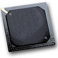
MPC564CZP40 Freescale Semiconductor, MPC564CZP40 Datasheet - Page 759

MPC564CZP40
Manufacturer Part Number
MPC564CZP40
Description
IC MPU 32BIT W/CODE COMP 388PBGA
Manufacturer
Freescale Semiconductor
Series
MPC5xxr
Specifications of MPC564CZP40
Core Processor
PowerPC
Core Size
32-Bit
Speed
40MHz
Connectivity
CAN, EBI/EMI, SCI, SPI, UART/USART
Peripherals
POR, PWM, WDT
Number Of I /o
56
Program Memory Size
512KB (512K x 8)
Program Memory Type
FLASH
Ram Size
32K x 8
Voltage - Supply (vcc/vdd)
2.5 V ~ 2.7 V
Data Converters
A/D 32x10b
Oscillator Type
External
Operating Temperature
-40°C ~ 85°C
Package / Case
388-BGA
Processor Series
MPC5xx
Core
PowerPC
Data Bus Width
32 bit
Data Ram Size
32 KB
Interface Type
CAN, JTAG, QSPI, SCI, SPI, UART
Maximum Clock Frequency
40 MHz
Number Of Programmable I/os
56
Number Of Timers
2
Operating Supply Voltage
0 V to 5 V
Maximum Operating Temperature
+ 85 C
Mounting Style
SMD/SMT
Minimum Operating Temperature
- 40 C
On-chip Adc
2 (10 bit, 32 Channel)
For Use With
MPC564EVB - KIT EVAL FOR MPC561/562/563/564
Lead Free Status / RoHS Status
Contains lead / RoHS non-compliant
Eeprom Size
-
Lead Free Status / Rohs Status
No
Available stocks
Company
Part Number
Manufacturer
Quantity
Price
Company:
Part Number:
MPC564CZP40
Manufacturer:
Freescale Semiconductor
Quantity:
10 000
- Current page: 759 of 1420
- Download datasheet (11Mb)
17.9.1
Freescale Semiconductor
•
•
•
•
•
•
•
MODE3
Counter buses
Versatile 16-bit dual action unit allowing up to two events to occur before software intervention is
required
Six software selectable modes allowing the MDASM to perform pulse width and period
measurements, PWM generation, single input capture and output compare operations as well as
port functions
Software selection of one of the four possible 16-bit counter buses used for timing operations
Flag setting and possible interrupt generation after MDASM action completion
Software selection of output pulse polarity
Software selection of totem-pole or open-drain output
Software readable output signal status
4 X 16-bit
MDASM Features
MODE2
Control register bits
Counter bus
select
Register B
MODE1
16-bit Register B1
16-bit Register B2
16-bit Register A
16-bit comparator B
16-bit comparator A
MPC561/MPC563 Reference Manual, Rev. 1.2
Figure 17-15. MDASM Block Diagram
BSL1 BSL0
MODE0
MIO Bus
FORCA FORCB
flip-flop
Output
Modular Input/Output Subsystem (MIOS14)
Request Bus
EDPOL
Output
detect
WOR
buffer
Edge
FLAG
Counter Bus Set
PIN
I/O signal
17-27
Related parts for MPC564CZP40
Image
Part Number
Description
Manufacturer
Datasheet
Request
R

Part Number:
Description:
MPC5 1K0 5%
Manufacturer:
TE Connectivity
Datasheet:

Part Number:
Description:
MPC5 500R 5%
Manufacturer:
TE Connectivity
Datasheet:

Part Number:
Description:
MPC5 5K0 5%
Manufacturer:
Tyco Electronics
Datasheet:

Part Number:
Description:
MPC5 5R0 5%
Manufacturer:
Tyco Electronics
Datasheet:

Part Number:
Description:
MPC5 50K 5%
Manufacturer:
Tyco Electronics
Datasheet:

Part Number:
Description:
MPC5 1R0 5%
Manufacturer:
Tyco Electronics
Datasheet:
Part Number:
Description:
Manufacturer:
Freescale Semiconductor, Inc
Datasheet:
Part Number:
Description:
Manufacturer:
Freescale Semiconductor, Inc
Datasheet:
Part Number:
Description:
Manufacturer:
Freescale Semiconductor, Inc
Datasheet:
Part Number:
Description:
Manufacturer:
Freescale Semiconductor, Inc
Datasheet:
Part Number:
Description:
Manufacturer:
Freescale Semiconductor, Inc
Datasheet:


