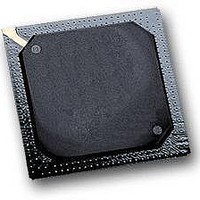
MPC564CZP40 Freescale Semiconductor, MPC564CZP40 Datasheet - Page 459

MPC564CZP40
Manufacturer Part Number
MPC564CZP40
Description
IC MPU 32BIT W/CODE COMP 388PBGA
Manufacturer
Freescale Semiconductor
Series
MPC5xxr
Specifications of MPC564CZP40
Core Processor
PowerPC
Core Size
32-Bit
Speed
40MHz
Connectivity
CAN, EBI/EMI, SCI, SPI, UART/USART
Peripherals
POR, PWM, WDT
Number Of I /o
56
Program Memory Size
512KB (512K x 8)
Program Memory Type
FLASH
Ram Size
32K x 8
Voltage - Supply (vcc/vdd)
2.5 V ~ 2.7 V
Data Converters
A/D 32x10b
Oscillator Type
External
Operating Temperature
-40°C ~ 85°C
Package / Case
388-BGA
Processor Series
MPC5xx
Core
PowerPC
Data Bus Width
32 bit
Data Ram Size
32 KB
Interface Type
CAN, JTAG, QSPI, SCI, SPI, UART
Maximum Clock Frequency
40 MHz
Number Of Programmable I/os
56
Number Of Timers
2
Operating Supply Voltage
0 V to 5 V
Maximum Operating Temperature
+ 85 C
Mounting Style
SMD/SMT
Minimum Operating Temperature
- 40 C
On-chip Adc
2 (10 bit, 32 Channel)
For Use With
MPC564EVB - KIT EVAL FOR MPC561/562/563/564
Lead Free Status / RoHS Status
Contains lead / RoHS non-compliant
Eeprom Size
-
Lead Free Status / Rohs Status
No
Available stocks
Company
Part Number
Manufacturer
Quantity
Price
Company:
Part Number:
MPC564CZP40
Manufacturer:
Freescale Semiconductor
Quantity:
10 000
- Current page: 459 of 1420
- Download datasheet (11Mb)
Note: This diagram represents the ILBS behavior when IRQMUX[0:1] = 11
The IRQMUX bits determine how many levels of IMB3 interrupts are sampled. Refer to
12.4.4
The interrupt synchronizer latches the 32 levels of interrupts from the IMB3 bus into a register which can
be read by the CPU or other U-bus master. Since there are only eight lines for interrupts on the IMB3 and
32 levels of interrupts are possible, the 32 interrupt levels are multiplexed onto eight IMB3 interrupt lines.
Apart from latching these interrupts in the register (UIPEND), the interrupt synchronizer drives the
interrupts onto the U-bus, where they are latched by the interrupt controller in the USIU.
If IMB3 modules drive interrupts on any of the 24 levels (levels eight through 31), they will be latched in
UIPEND in the UIMB. If any of the register bits 7 to 31 are set, then bit 7 will be set as well.
Freescale Semiconductor
IRQMUX[0:1]
ILBS [0:1]
IMB3 CLOCK
IMB3 LVL[0:7]
Interrupt Synchronizer
00
01
10
11
Figure 12-5. Time-Multiplexing Protocol for IRQ Signals
00, 00, 00.....
00, 01, 00, 01....
00, 01, 10, 00, 01, 10,.....
00, 01, 10, 11, 00, 01, 10, 11,....
ILBS[0:1]
00
01
10
11
00
MPC561/MPC563 Reference Manual, Rev. 1.2
ILBS sequence
Table 12-3. ILBS Signal Functionality
Table 12-4. IRQMUX Functionality
IMB3 interrupt sources mapped onto 0:7 levels will
drive interrupts onto IMB3 LVL[0:7]
IMB3 interrupt sources mapped onto 8:15 levels will
drive interrupts onto IMB3 LVL[0:7]
IMB3 interrupt sources mapped onto 16:23 levels will
drive interrupts onto IMB3 LVL[0:7]
IMB3 interrupt sources mapped onto 24:31 levels will
drive interrupts onto IMB3 LVL[0:7]
01
LVL
[0:7]
10
LVL
[8:15]
16:23
11
LVL
Description
Latch 0:7 IMB3 interrupt levels
Latch 0:15 IMB3 interrupt levels
Latch 0:23 IMB3 interrupt levels
Latch 0:31 IMB3 interrupt levels
24:31
LVL
00
01
LVL
0:7
Description
10
U-Bus to IMB3 Bus Interface (UIMB)
11
Table
12-4.
12-5
Related parts for MPC564CZP40
Image
Part Number
Description
Manufacturer
Datasheet
Request
R

Part Number:
Description:
MPC5 1K0 5%
Manufacturer:
TE Connectivity
Datasheet:

Part Number:
Description:
MPC5 500R 5%
Manufacturer:
TE Connectivity
Datasheet:

Part Number:
Description:
MPC5 5K0 5%
Manufacturer:
Tyco Electronics
Datasheet:

Part Number:
Description:
MPC5 5R0 5%
Manufacturer:
Tyco Electronics
Datasheet:

Part Number:
Description:
MPC5 50K 5%
Manufacturer:
Tyco Electronics
Datasheet:

Part Number:
Description:
MPC5 1R0 5%
Manufacturer:
Tyco Electronics
Datasheet:
Part Number:
Description:
Manufacturer:
Freescale Semiconductor, Inc
Datasheet:
Part Number:
Description:
Manufacturer:
Freescale Semiconductor, Inc
Datasheet:
Part Number:
Description:
Manufacturer:
Freescale Semiconductor, Inc
Datasheet:
Part Number:
Description:
Manufacturer:
Freescale Semiconductor, Inc
Datasheet:
Part Number:
Description:
Manufacturer:
Freescale Semiconductor, Inc
Datasheet:


