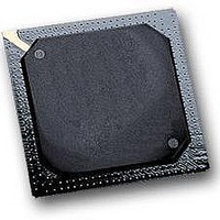
MPC564CZP40 Freescale Semiconductor, MPC564CZP40 Datasheet - Page 329

MPC564CZP40
Manufacturer Part Number
MPC564CZP40
Description
IC MPU 32BIT W/CODE COMP 388PBGA
Manufacturer
Freescale Semiconductor
Series
MPC5xxr
Specifications of MPC564CZP40
Core Processor
PowerPC
Core Size
32-Bit
Speed
40MHz
Connectivity
CAN, EBI/EMI, SCI, SPI, UART/USART
Peripherals
POR, PWM, WDT
Number Of I /o
56
Program Memory Size
512KB (512K x 8)
Program Memory Type
FLASH
Ram Size
32K x 8
Voltage - Supply (vcc/vdd)
2.5 V ~ 2.7 V
Data Converters
A/D 32x10b
Oscillator Type
External
Operating Temperature
-40°C ~ 85°C
Package / Case
388-BGA
Processor Series
MPC5xx
Core
PowerPC
Data Bus Width
32 bit
Data Ram Size
32 KB
Interface Type
CAN, JTAG, QSPI, SCI, SPI, UART
Maximum Clock Frequency
40 MHz
Number Of Programmable I/os
56
Number Of Timers
2
Operating Supply Voltage
0 V to 5 V
Maximum Operating Temperature
+ 85 C
Mounting Style
SMD/SMT
Minimum Operating Temperature
- 40 C
On-chip Adc
2 (10 bit, 32 Channel)
For Use With
MPC564EVB - KIT EVAL FOR MPC561/562/563/564
Lead Free Status / RoHS Status
Contains lead / RoHS non-compliant
Eeprom Size
-
Lead Free Status / Rohs Status
No
Available stocks
Company
Part Number
Manufacturer
Quantity
Price
Company:
Part Number:
MPC564CZP40
Manufacturer:
Freescale Semiconductor
Quantity:
10 000
- Current page: 329 of 1420
- Download datasheet (11Mb)
Figure 8-13
8.9
A special circuit for IRAMSTBY supply failure detection is provided. In the case of supply failure
detection, the dedicated sticky bits LVSRS in the VSRMCR register are asserted. Software can read or
clear these bits. The user should enable the detector and then clear these bits. If any of the LVSR bits are
read as one, then a power failure of IRAMSTBY has occurred. The circuit is capable of detecting supply
failure below a voltage level to be determined. Also, enable/disable control bit for the IRAMSTBY
detector may be used to disconnect the circuit and save the detector power consumption.
8.10
Figure 8-14
operation. Note that for each of the conditions detailing the voltage relationships the absolute bounds of
the minimum and maximum voltage supply cannot be violated; that is, the value of VDDL cannot fall
below 2.5 V or exceed 2.7 V, and the value of VDDH cannot fall below 4.75 V or exceed 5.25 V for normal
operation. Power consumption during power up sequencing will be below the operating power
consumption.
Freescale Semiconductor
SPR 268, 269,
SPR Number
Address or
0x2F C288
284, 285,
SPR 22
IRAMSTBY Supply Failure Detection
Power-Up/Down Sequencing
Write to the key other value
illustrates the process of locking or unlocking a register powered by KAPWR.
and
(Valid for other registers)
Figure 8-15
Power-On Reset
See
Decrementer
See
(DEC)” for bit descriptions.
Time Base
See
(TB),” for bit descriptions.
Reset Status Register (RSR)
KAPWR Register
Section 3.9.5, “Decrementer Register
Table 7-3
Section 6.2.2.4.2, “Time Base SPRs
Table 8-8. KAPWR Registers and Key Registers (continued)
Figure 8-13. Keep-Alive Register Key State Diagram
detail the power-up sequencing for MPC561/MPC563 during normal
for bit descriptions.
Register
MPC561/MPC563 Reference Manual, Rev. 1.2
Locked
Open
0x2F C30C Time Base and Decrementer Key (TBK)
0x2F C388
Address
Write to the Key 0x55CCAA33
Reset Status Register Key (RSRK)
Associated Key Register
(Valid for RTC, RTSEC,
RTCAL and RTCSC)
Power On Reset
Register
Clocks and Power Control
8-27
Related parts for MPC564CZP40
Image
Part Number
Description
Manufacturer
Datasheet
Request
R

Part Number:
Description:
MPC5 1K0 5%
Manufacturer:
TE Connectivity
Datasheet:

Part Number:
Description:
MPC5 500R 5%
Manufacturer:
TE Connectivity
Datasheet:

Part Number:
Description:
MPC5 5K0 5%
Manufacturer:
Tyco Electronics
Datasheet:

Part Number:
Description:
MPC5 5R0 5%
Manufacturer:
Tyco Electronics
Datasheet:

Part Number:
Description:
MPC5 50K 5%
Manufacturer:
Tyco Electronics
Datasheet:

Part Number:
Description:
MPC5 1R0 5%
Manufacturer:
Tyco Electronics
Datasheet:
Part Number:
Description:
Manufacturer:
Freescale Semiconductor, Inc
Datasheet:
Part Number:
Description:
Manufacturer:
Freescale Semiconductor, Inc
Datasheet:
Part Number:
Description:
Manufacturer:
Freescale Semiconductor, Inc
Datasheet:
Part Number:
Description:
Manufacturer:
Freescale Semiconductor, Inc
Datasheet:
Part Number:
Description:
Manufacturer:
Freescale Semiconductor, Inc
Datasheet:


