IPSR-VIDEO Altera, IPSR-VIDEO Datasheet - Page 42

IPSR-VIDEO
Manufacturer Part Number
IPSR-VIDEO
Description
RENEWAL Of IPS-VIDEO
Manufacturer
Altera
Series
IP Suitesr
Datasheet
1.IPS-VIDEO.pdf
(202 pages)
Specifications of IPSR-VIDEO
Software Application
IP CORE, SUITES
Supported Families
Arria GX, Cyclone II, HardCopy II, Stratix II
Features
Common Avalon Streaming (Avalon-St) Interface And Avalon-St Video Protocol
Core Architecture
FPGA
Core Sub-architecture
Arria, Cyclone, Stratix
Rohs Compliant
NA
Lead Free Status / RoHS Status
na
- Current page: 42 of 202
- Download datasheet (6Mb)
3–6
Clocked Video Input
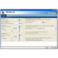
Table 3–7. Clocked Video Input Parameter Settings
Video and Image Processing Suite User Guide
Select preset to load
Bits per pixel per color
plane
Number of color planes
Color plane transmission
format
Field order
Interlaced or progressive
Width
Height, Frame / Field 0
Height, Field 1
Sync Signals
Allow color planes in
sequence input
Generate
synchronization outputs
Width of bus “vid_std”
Extract ancillary packets
Pixel FIFO size
Video in and out use the
same clock
Use control port
Parameter
Table 3–7
DVI 1080p60,
SDI 1080p60,
SDI 1080i60,
PAL, NTSC
4–20, Default = 8
1–4, Default = 3
Sequence, Parallel
Field 0 first,
Field 1 first,
Any field first,
Progressive,
Interlaced
32–65,536,
Default = 1,920
32–65,536,
Default = 1,080
32–65,536, Default
= 1,080
Embedded in video,
On separate wires
On or Off
No, Yes, Only
1 - 16
On or Off
32–(memory limit),
Default = 1,920
On or Off
On or Off
Value
shows the Clocked Video Input MegaCore function parameters.
You can choose from a list of preset conversions or use the other fields in
the dialog box to set up custom parameter values. If you click Load values
into controls the dialog box is initialized with values for the selected preset
conversion.
Choose the number of bits per pixel (per color plane).
Choose the number of color planes.
Choose whether the color planes are transmitted in sequence or in
parallel.
Choose the field to synchronize to first when starting or stopping the
output.
Choose the format to be used when no format can be automatically
detected.
Choose the image width to be used when no format can be automatically
detected.
Choose the image height to be used when no format can be automatically
detected.
Choose the image height for interlaced field 1when no format can be
automatically detected.
Choose whether the synchronization signal is embedded in the video
stream or provided on a separate wire.
Choose whether run-time switching is allowed between sequential and
parallel color plane transmission formats. The format is controlled by the
vid_hd_sdn signal.
Specifies whether the Avalon-ST output and synchronization outputs (sof,
sof_locked, refclk_div) are generated:
■
■
■
The width, in bits, of the vid_std bus.
Specifies whether ancillary packets are extracted in embedded sync mode.
Choose the required FIFO depth in pixels (limited by the available on-chip
memory).
Turn on if you want to use the same signal for the input and output video
image stream clocks.
Turn on to use the optional stop/go control port.
No—Only Avalon-ST Video output
Yes—Avalon-ST Video output and synchronization outputs
Only—Only synchronization outputs
Description
January 2011 Altera Corporation
Chapter 3: Parameter Settings
Clocked Video Input
Related parts for IPSR-VIDEO
Image
Part Number
Description
Manufacturer
Datasheet
Request
R

Part Number:
Description:
CYCLONE II STARTER KIT EP2C20N
Manufacturer:
Altera
Datasheet:

Part Number:
Description:
CPLD, EP610 Family, ECMOS Process, 300 Gates, 16 Macro Cells, 16 Reg., 16 User I/Os, 5V Supply, 35 Speed Grade, 24DIP
Manufacturer:
Altera Corporation
Datasheet:

Part Number:
Description:
CPLD, EP610 Family, ECMOS Process, 300 Gates, 16 Macro Cells, 16 Reg., 16 User I/Os, 5V Supply, 15 Speed Grade, 24DIP
Manufacturer:
Altera Corporation
Datasheet:

Part Number:
Description:
Manufacturer:
Altera Corporation
Datasheet:

Part Number:
Description:
CPLD, EP610 Family, ECMOS Process, 300 Gates, 16 Macro Cells, 16 Reg., 16 User I/Os, 5V Supply, 30 Speed Grade, 24DIP
Manufacturer:
Altera Corporation
Datasheet:

Part Number:
Description:
High-performance, low-power erasable programmable logic devices with 8 macrocells, 10ns
Manufacturer:
Altera Corporation
Datasheet:

Part Number:
Description:
High-performance, low-power erasable programmable logic devices with 8 macrocells, 7ns
Manufacturer:
Altera Corporation
Datasheet:

Part Number:
Description:
Classic EPLD
Manufacturer:
Altera Corporation
Datasheet:

Part Number:
Description:
High-performance, low-power erasable programmable logic devices with 8 macrocells, 10ns
Manufacturer:
Altera Corporation
Datasheet:

Part Number:
Description:
Manufacturer:
Altera Corporation
Datasheet:

Part Number:
Description:
Manufacturer:
Altera Corporation
Datasheet:


