R0K561622S000BE Renesas Electronics America, R0K561622S000BE Datasheet - Page 797
R0K561622S000BE
Manufacturer Part Number
R0K561622S000BE
Description
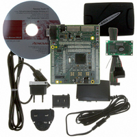
KIT STARTER FOR H8SX/1622
Manufacturer
Renesas Electronics America
Series
Renesas Starter Kits (RSK)r
Type
MCUr
Specifications of R0K561622S000BE
Contents
Board, Cables, CD, Debugger, Power Supply
Silicon Manufacturer
Renesas
Features
Coding And Debugging, E10A Emulator, RS232 Serial Connection
Kit Contents
Board
Silicon Family Name
H8SX/1622F
Silicon Core Number
R5F61622N50LGV
Lead Free Status / RoHS Status
Lead free / RoHS Compliant
For Use With/related Products
H8SX/1622
Lead Free Status / RoHS Status
Lead free / RoHS Compliant, Lead free / RoHS Compliant


19.6
19.6.1
Operation of the ∆Σ A/D converter can be enabled or disabled by setting the module stop control
register. By default, the ∆Σ A/D converter is stopped. Most registers of the ∆Σ A/D converter only
become accessible when it is released from the module stop state. See section 24, Power-Down
Modes, for details.
Although DSADMR is accessible to the CPU at any time, writing to this register should only be
performed while the converter is in the module stop state.
To stop the ∆Σ A/D converter completely, place it in the module stop state and then stop the
biasing circuit by clearing the BIASE bit in DSADMR to 0.
19.6.2
When the BIASE bit in DSADMR is set to enable the biasing circuit before the ∆Σ A/D converter
is used, a certain period must be secured for stabilization of the biasing circuit. If A/D conversion
is executed without ensuring enough time for stabilization of the biasing circuit, the precision of
A/D conversion is not guaranteed.
When the biasing circuit is stopped by clearing the BIASE bit in DSADMR to 0 or on entry to the
hardware standby mode, the reset state, or deep software standby mode, a certain period for
stabilization of the biasing circuit will be required after the BIASE bit has been set to 1 again.
A certain amount of biasing current flows while the biasing circuit is running. Since the value set
in the BIASE bit is retained in software standby mode, the supply current will include the current
that flows through the biasing circuit if BIASE = 1. Be sure to set the BIASE bit appropriately
before initiating software standby mode.
Ensure at least 20 ms for stabilization of the biasing circuit.
Usage Notes
Module Stop Function Setting
Settings for the Biasing Circuit
Rev. 2.00 Sep. 16, 2009 Page 767 of 1036
Section 19 ∆Σ A/D Converter
REJ09B0414-0200
Related parts for R0K561622S000BE
Image
Part Number
Description
Manufacturer
Datasheet
Request
R

Part Number:
Description:
KIT STARTER FOR M16C/29
Manufacturer:
Renesas Electronics America
Datasheet:

Part Number:
Description:
KIT STARTER FOR R8C/2D
Manufacturer:
Renesas Electronics America
Datasheet:

Part Number:
Description:
R0K33062P STARTER KIT
Manufacturer:
Renesas Electronics America
Datasheet:

Part Number:
Description:
KIT STARTER FOR R8C/23 E8A
Manufacturer:
Renesas Electronics America
Datasheet:

Part Number:
Description:
KIT STARTER FOR R8C/25
Manufacturer:
Renesas Electronics America
Datasheet:

Part Number:
Description:
KIT STARTER H8S2456 SHARPE DSPLY
Manufacturer:
Renesas Electronics America
Datasheet:

Part Number:
Description:
KIT STARTER FOR R8C38C
Manufacturer:
Renesas Electronics America
Datasheet:

Part Number:
Description:
KIT STARTER FOR R8C35C
Manufacturer:
Renesas Electronics America
Datasheet:

Part Number:
Description:
KIT STARTER FOR R8CL3AC+LCD APPS
Manufacturer:
Renesas Electronics America
Datasheet:
Part Number:
Description:
KIT STARTER FOR RX610
Manufacturer:
Renesas Electronics America
Datasheet:

Part Number:
Description:
KIT STARTER FOR R32C/118
Manufacturer:
Renesas Electronics America
Datasheet:

Part Number:
Description:
KIT DEV RSK-R8C/26-29
Manufacturer:
Renesas Electronics America
Datasheet:

Part Number:
Description:
KIT STARTER FOR SH7124
Manufacturer:
Renesas Electronics America
Datasheet:

Part Number:
Description:
KIT DEV FOR SH7203
Manufacturer:
Renesas Electronics America
Datasheet:
Part Number:
Description:
KIT STARTER FOR R8C/18191A1B
Manufacturer:
Renesas Electronics America
Datasheet: