R0K561622S000BE Renesas Electronics America, R0K561622S000BE Datasheet - Page 98
R0K561622S000BE
Manufacturer Part Number
R0K561622S000BE
Description
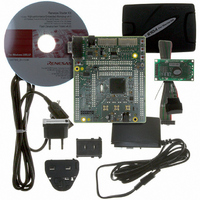
KIT STARTER FOR H8SX/1622
Manufacturer
Renesas Electronics America
Series
Renesas Starter Kits (RSK)r
Type
MCUr
Specifications of R0K561622S000BE
Contents
Board, Cables, CD, Debugger, Power Supply
Silicon Manufacturer
Renesas
Features
Coding And Debugging, E10A Emulator, RS232 Serial Connection
Kit Contents
Board
Silicon Family Name
H8SX/1622F
Silicon Core Number
R5F61622N50LGV
Lead Free Status / RoHS Status
Lead free / RoHS Compliant
For Use With/related Products
H8SX/1622
Lead Free Status / RoHS Status
Lead free / RoHS Compliant, Lead free / RoHS Compliant


Section 2 CPU
2.9
The H8SX CPU has five main processing states: the reset state, exception-handling state, program
execution state, bus-released state, and program stop state. Figure 2.16 indicates the state
transitions.
• Reset state
• Exception-handling state
• Program execution state
• Bus-released state
• Program stop state
Rev. 2.00 Sep. 16, 2009 Page 68 of 1036
REJ09B0414-0200
In this state the CPU and internal peripheral modules are all initialized and stopped. When the
RES input goes low, all current processing stops and the CPU enters the reset state. All
interrupts are masked in the reset state. Reset exception handling starts when the RES signal
changes from low to high. For details, see section 4, Resets and section 5, Exception Handling.
The exception-handling state is a transient state that occurs when the CPU alters the normal
processing flow due to activation of an exception source, such as, a reset, trace, interrupt, or
trap instruction. The CPU fetches a start address (vector) from the exception handling vector
table and branches to that address. For further details, see section 4, Resets and section 5,
Exception Handling.
In this state the CPU executes program instructions in sequence.
The bus-released state occurs when the bus has been released in response to a bus request from
a bus master other than the CPU. While the bus is released, the CPU halts operations.
This is a power-down state in which the CPU stops operating. The program stop state occurs
when a SLEEP instruction is executed or the CPU enters hardware standby mode. For details,
see section 24, Power-Down Modes.
Request for exception
Note: In any state, when the STBY signal goes low, a transition to the hardware standby mode occurs.
Processing States
* In any state except the hardware standby mode, when the RES signal goes low, a transition
handling
to the reset state occurs. A transition to the reset state can also be made without driving
the RES signal low. For details, see section 4, Resets.
Program execution
Exception-handling
state
state
RES = high
End of exception
handling
Figure 2.16 State Transitions
Interrupt
request
SLEEP instruction
bus request
Reset state*
End of
request
Bus
RES = low
Bus request
Program stop state
Bus-released state
End of bus request
Related parts for R0K561622S000BE
Image
Part Number
Description
Manufacturer
Datasheet
Request
R

Part Number:
Description:
KIT STARTER FOR M16C/29
Manufacturer:
Renesas Electronics America
Datasheet:

Part Number:
Description:
KIT STARTER FOR R8C/2D
Manufacturer:
Renesas Electronics America
Datasheet:

Part Number:
Description:
R0K33062P STARTER KIT
Manufacturer:
Renesas Electronics America
Datasheet:

Part Number:
Description:
KIT STARTER FOR R8C/23 E8A
Manufacturer:
Renesas Electronics America
Datasheet:

Part Number:
Description:
KIT STARTER FOR R8C/25
Manufacturer:
Renesas Electronics America
Datasheet:

Part Number:
Description:
KIT STARTER H8S2456 SHARPE DSPLY
Manufacturer:
Renesas Electronics America
Datasheet:

Part Number:
Description:
KIT STARTER FOR R8C38C
Manufacturer:
Renesas Electronics America
Datasheet:

Part Number:
Description:
KIT STARTER FOR R8C35C
Manufacturer:
Renesas Electronics America
Datasheet:

Part Number:
Description:
KIT STARTER FOR R8CL3AC+LCD APPS
Manufacturer:
Renesas Electronics America
Datasheet:
Part Number:
Description:
KIT STARTER FOR RX610
Manufacturer:
Renesas Electronics America
Datasheet:

Part Number:
Description:
KIT STARTER FOR R32C/118
Manufacturer:
Renesas Electronics America
Datasheet:

Part Number:
Description:
KIT DEV RSK-R8C/26-29
Manufacturer:
Renesas Electronics America
Datasheet:

Part Number:
Description:
KIT STARTER FOR SH7124
Manufacturer:
Renesas Electronics America
Datasheet:

Part Number:
Description:
KIT DEV FOR SH7203
Manufacturer:
Renesas Electronics America
Datasheet:
Part Number:
Description:
KIT STARTER FOR R8C/18191A1B
Manufacturer:
Renesas Electronics America
Datasheet: