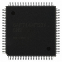
HD64F7144F50V Renesas Electronics America, HD64F7144F50V Datasheet - Page 922

HD64F7144F50V
Manufacturer Part Number
HD64F7144F50V
Description
IC SUPERH MCU FLASH 256K 112QFP
Manufacturer
Renesas Electronics America
Series
SuperH® SH7144r
Specifications of HD64F7144F50V
Core Processor
SH-2
Core Size
32-Bit
Speed
50MHz
Connectivity
EBI/EMI, I²C, SCI
Peripherals
DMA, POR, PWM, WDT
Number Of I /o
74
Program Memory Size
256KB (256K x 8)
Program Memory Type
FLASH
Ram Size
8K x 8
Voltage - Supply (vcc/vdd)
3 V ~ 3.6 V
Data Converters
A/D 8x10b
Oscillator Type
Internal
Operating Temperature
-20°C ~ 75°C
Package / Case
112-QFP
For Use With
HS0005KCU11H - EMULATOR E10A-USB H8S(X),SH2(A)EDK7145 - DEV EVALUATION KIT SH7145
Lead Free Status / RoHS Status
Lead free / RoHS Compliant
Eeprom Size
-
Available stocks
Company
Part Number
Manufacturer
Quantity
Price
Company:
Part Number:
HD64F7144F50V
Manufacturer:
RENESAS
Quantity:
450
Company:
Part Number:
HD64F7144F50V
Manufacturer:
Renesas Electronics America
Quantity:
10 000
Part Number:
HD64F7144F50V
Manufacturer:
RENESAS/瑞萨
Quantity:
20 000
- Current page: 922 of 932
- Download datasheet (6Mb)
Main Revisions for this Edition
Rev.4.00 Mar. 27, 2008 Page 876 of 882
REJ09B0108-0400
Item
15.3.2 A/D Control/Status
Register_0, 1 (ADCSR_0,
ADCSR_1)
16.2.2 Compare Match
Timer Control/Status
Register_0, 1 (CMCSR_0,
CMCSR_1)
19.1 Features
19.8.3 Interrupt Handling
when
Programming/Erasing
Flash Memory
Figure 19.10
Erase/Erase-Verify
Flowchart
19.11.3 Notes on Flash
Memory Programming and
Erasing
23.5.7 Settings of AUD-
Related Pins when Using
E10A
657
Page Revision (See Manual for Details)
545
561
679
683
to
685
717
Table amended
Table amended
Description amended
•
Figure amended
Description replaced
Newly added
Bit
7
Bit
7
Reprogramming capability
See section 26.5, Flash Memory Characteristics.
Bit Name Initial Value
ADF
Bit Name Initial Value
CMF
0
0
R/W
R/(W)*
R/W
R/(W)* Compare Match Flag
Description
A/D End Flag
A status flag that indicates the end of A/D conversion.
[Setting conditions]
•
•
[Clearing conditions]
•
•
Description
This flag indicates whether or not the CMCNT and
CMCOR values have matched.
0: CMCNT and CMCOR values have not matched
1: CMCNT and CMCOR values have matched
[Clearing condition]
•
•
When A/D conversion ends in single mode
When A/D conversion ends on all specified
channels in scan mode
When 0 is written after reading ADF = 1
When the DMAC or the DTC is activated by an
ADI interrupt and data is read from ADDR while
the DTMR bit in the DTC is cleared to 0
Write 0 to CMF after reading 1 from it
When the DTC is activated by an CMI interrupt
and data is transferred with the DISEL bit in
DTMR of DTC = 0
Set EBR1 and EBR2
Wait (t
SWE bit ← 1
Erase start
n ← 1
SSWE
) μs
* 1
* 3
Related parts for HD64F7144F50V
Image
Part Number
Description
Manufacturer
Datasheet
Request
R

Part Number:
Description:
KIT STARTER FOR M16C/29
Manufacturer:
Renesas Electronics America
Datasheet:

Part Number:
Description:
KIT STARTER FOR R8C/2D
Manufacturer:
Renesas Electronics America
Datasheet:

Part Number:
Description:
R0K33062P STARTER KIT
Manufacturer:
Renesas Electronics America
Datasheet:

Part Number:
Description:
KIT STARTER FOR R8C/23 E8A
Manufacturer:
Renesas Electronics America
Datasheet:

Part Number:
Description:
KIT STARTER FOR R8C/25
Manufacturer:
Renesas Electronics America
Datasheet:

Part Number:
Description:
KIT STARTER H8S2456 SHARPE DSPLY
Manufacturer:
Renesas Electronics America
Datasheet:

Part Number:
Description:
KIT STARTER FOR R8C38C
Manufacturer:
Renesas Electronics America
Datasheet:

Part Number:
Description:
KIT STARTER FOR R8C35C
Manufacturer:
Renesas Electronics America
Datasheet:

Part Number:
Description:
KIT STARTER FOR R8CL3AC+LCD APPS
Manufacturer:
Renesas Electronics America
Datasheet:

Part Number:
Description:
KIT STARTER FOR RX610
Manufacturer:
Renesas Electronics America
Datasheet:

Part Number:
Description:
KIT STARTER FOR R32C/118
Manufacturer:
Renesas Electronics America
Datasheet:

Part Number:
Description:
KIT DEV RSK-R8C/26-29
Manufacturer:
Renesas Electronics America
Datasheet:

Part Number:
Description:
KIT STARTER FOR SH7124
Manufacturer:
Renesas Electronics America
Datasheet:

Part Number:
Description:
KIT STARTER FOR H8SX/1622
Manufacturer:
Renesas Electronics America
Datasheet:


