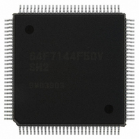
HD64F7144F50V Renesas Electronics America, HD64F7144F50V Datasheet - Page 14

HD64F7144F50V
Manufacturer Part Number
HD64F7144F50V
Description
IC SUPERH MCU FLASH 256K 112QFP
Manufacturer
Renesas Electronics America
Series
SuperH® SH7144r
Specifications of HD64F7144F50V
Core Processor
SH-2
Core Size
32-Bit
Speed
50MHz
Connectivity
EBI/EMI, I²C, SCI
Peripherals
DMA, POR, PWM, WDT
Number Of I /o
74
Program Memory Size
256KB (256K x 8)
Program Memory Type
FLASH
Ram Size
8K x 8
Voltage - Supply (vcc/vdd)
3 V ~ 3.6 V
Data Converters
A/D 8x10b
Oscillator Type
Internal
Operating Temperature
-20°C ~ 75°C
Package / Case
112-QFP
For Use With
HS0005KCU11H - EMULATOR E10A-USB H8S(X),SH2(A)EDK7145 - DEV EVALUATION KIT SH7145
Lead Free Status / RoHS Status
Lead free / RoHS Compliant
Eeprom Size
-
Available stocks
Company
Part Number
Manufacturer
Quantity
Price
Company:
Part Number:
HD64F7144F50V
Manufacturer:
RENESAS
Quantity:
450
Company:
Part Number:
HD64F7144F50V
Manufacturer:
Renesas Electronics America
Quantity:
10 000
Part Number:
HD64F7144F50V
Manufacturer:
RENESAS/瑞萨
Quantity:
20 000
- Current page: 14 of 932
- Download datasheet (6Mb)
7.5
Section 8 Data Transfer Controller (DTC) ........................................................113
8.1
8.2
8.3
8.4
8.5
Section 9 Bus State Controller (BSC) ...............................................................137
9.1
9.2
9.3
9.4
Rev.4.00 Mar. 27, 2008 Page xii of xliv
REJ09B0108-0400
Usage Notes ...................................................................................................................... 111
7.5.1
7.5.2
7.5.3
7.5.4
7.5.5
Features............................................................................................................................. 113
Register Descriptions ........................................................................................................ 115
8.2.1
8.2.2
8.2.3
8.2.4
8.2.5
8.2.6
8.2.7
8.2.8
8.2.9
Operation .......................................................................................................................... 122
8.3.1
8.3.2
8.3.3
8.3.4
8.3.5
8.3.6
Procedures for Using DTC................................................................................................ 134
8.4.1
8.4.2
8.4.3
Usage Notes ...................................................................................................................... 136
8.5.1
8.5.2
8.5.3
Features............................................................................................................................. 137
Input/Output Pins .............................................................................................................. 139
Register Configuration...................................................................................................... 140
Address Map ..................................................................................................................... 141
Simultaneous Fetching of Two Instructions ........................................................ 111
Instruction Fetches at Branches ........................................................................... 111
Contention between User Break and Exception Processing ................................ 112
Break at Non-Delay Branch Instruction Jump Destination.................................. 112
Module Standby Mode Setting ............................................................................ 112
DTC Mode Register (DTMR).............................................................................. 116
DTC Source Address Register (DTSAR) ............................................................ 118
DTC Destination Address Register (DTDAR) .................................................... 118
DTC Initial Address Register (DTIAR)............................................................... 118
DTC Transfer Count Register A (DTCRA) ......................................................... 118
DTC Transfer Count Register B (DTCRB) ......................................................... 119
DTC Enable Registers (DTER)............................................................................ 119
DTC Control/Status Register (DTCSR)............................................................... 120
DTC Information Base Register (DTBR) ............................................................ 121
Activation Sources............................................................................................... 122
Location of Register Information and DTC Vector Table ................................... 122
DTC Operation .................................................................................................... 125
Interrupt Source ................................................................................................... 132
Operation Timing................................................................................................. 132
DTC Execution State Counts ............................................................................... 133
Activation by Interrupt......................................................................................... 134
Activation by Software ........................................................................................ 134
DTC Use Example ............................................................................................... 135
Prohibition against DMAC/DTC Register Access by DTC................................. 136
Module Standby Mode Setting ............................................................................ 136
On-Chip RAM ..................................................................................................... 136
Related parts for HD64F7144F50V
Image
Part Number
Description
Manufacturer
Datasheet
Request
R

Part Number:
Description:
KIT STARTER FOR M16C/29
Manufacturer:
Renesas Electronics America
Datasheet:

Part Number:
Description:
KIT STARTER FOR R8C/2D
Manufacturer:
Renesas Electronics America
Datasheet:

Part Number:
Description:
R0K33062P STARTER KIT
Manufacturer:
Renesas Electronics America
Datasheet:

Part Number:
Description:
KIT STARTER FOR R8C/23 E8A
Manufacturer:
Renesas Electronics America
Datasheet:

Part Number:
Description:
KIT STARTER FOR R8C/25
Manufacturer:
Renesas Electronics America
Datasheet:

Part Number:
Description:
KIT STARTER H8S2456 SHARPE DSPLY
Manufacturer:
Renesas Electronics America
Datasheet:

Part Number:
Description:
KIT STARTER FOR R8C38C
Manufacturer:
Renesas Electronics America
Datasheet:

Part Number:
Description:
KIT STARTER FOR R8C35C
Manufacturer:
Renesas Electronics America
Datasheet:

Part Number:
Description:
KIT STARTER FOR R8CL3AC+LCD APPS
Manufacturer:
Renesas Electronics America
Datasheet:

Part Number:
Description:
KIT STARTER FOR RX610
Manufacturer:
Renesas Electronics America
Datasheet:

Part Number:
Description:
KIT STARTER FOR R32C/118
Manufacturer:
Renesas Electronics America
Datasheet:

Part Number:
Description:
KIT DEV RSK-R8C/26-29
Manufacturer:
Renesas Electronics America
Datasheet:

Part Number:
Description:
KIT STARTER FOR SH7124
Manufacturer:
Renesas Electronics America
Datasheet:

Part Number:
Description:
KIT STARTER FOR H8SX/1622
Manufacturer:
Renesas Electronics America
Datasheet:


