HD64F7144F50V Renesas Electronics America, HD64F7144F50V Datasheet - Page 21
HD64F7144F50V
Manufacturer Part Number
HD64F7144F50V
Description
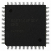
IC SUPERH MCU FLASH 256K 112QFP
Manufacturer
Renesas Electronics America
Series
SuperH® SH7144r
Specifications of HD64F7144F50V
Core Processor
SH-2
Core Size
32-Bit
Speed
50MHz
Connectivity
EBI/EMI, I²C, SCI
Peripherals
DMA, POR, PWM, WDT
Number Of I /o
74
Program Memory Size
256KB (256K x 8)
Program Memory Type
FLASH
Ram Size
8K x 8
Voltage - Supply (vcc/vdd)
3 V ~ 3.6 V
Data Converters
A/D 8x10b
Oscillator Type
Internal
Operating Temperature
-20°C ~ 75°C
Package / Case
112-QFP
For Use With
HS0005KCU11H - EMULATOR E10A-USB H8S(X),SH2(A)EDK7145 - DEV EVALUATION KIT SH7145
Lead Free Status / RoHS Status
Lead free / RoHS Compliant
Eeprom Size
-
Available stocks
Company
Part Number
Manufacturer
Quantity
Price
Company:

Part Number:
HD64F7144F50V
Manufacturer:
RENESAS
Quantity:
450
Company:
Part Number:
HD64F7144F50V
Manufacturer:
Renesas Electronics America
Quantity:
10 000
Part Number:
HD64F7144F50V
Manufacturer:
RENESAS/瑞萨
Quantity:
20 000


15.5 Interrupt Sources and DTC, DMAC Transfer Requests....................................................553
15.6 Definitions of A/D Conversion Accuracy .........................................................................554
15.7 Usage Notes ......................................................................................................................556
Section 16 Compare Match Timer (CMT)........................................................ 559
16.1 Features .............................................................................................................................559
16.2 Register Descriptions ........................................................................................................560
16.3 Operation...........................................................................................................................563
16.4 Interrupts ...........................................................................................................................564
16.5 Usage Notes ......................................................................................................................566
Section 17 Pin Function Controller (PFC)........................................................ 569
17.1 Register Descriptions ........................................................................................................595
15.4.6 External Trigger Input Timing .............................................................................552
15.7.1 Module Standby Mode Setting.............................................................................556
15.7.2 Permissible Signal Source Impedance .................................................................556
15.7.3 Influences on Absolute Accuracy ........................................................................556
15.7.4 Range of Analog Power Supply and Other Pin Settings ......................................557
15.7.5 Notes on Board Design ........................................................................................557
15.7.6 Notes on Noise Countermeasures ........................................................................557
16.2.1 Compare Match Timer Start Register (CMSTR) .................................................560
16.2.2 Compare Match Timer Control/Status Register_0, 1
16.2.3 Compare Match Timer Counter_0, 1 (CMCNT_0, CMCNT_1) .........................562
16.2.4 Compare Match Timer Constant Register_0, 1 (CMCOR_0, CMCOR_1) .........562
16.3.1 Compare Match Counter Operation .....................................................................563
16.3.2 CMCNT Count Timing........................................................................................563
16.4.1 Interrupt Sources and DTC Activation ................................................................564
16.4.2 Compare Match Flag Set Timing.........................................................................564
16.4.3 Compare Match Flag Clear Timing .....................................................................565
16.5.1 Contention between CMCNT Write and Compare Match ...................................566
16.5.2 Contention between CMCNT Word Write and Counter Incrementation.............567
16.5.3 Contention between CMCNT Byte Write and Counter Incrementation ..............568
17.1.1 Port A I/O Register L, H (PAIORL, PAIORH) ...................................................596
17.1.2 Port A Control Registers L2, L1, H (PACRL2, PACRL1, PACRH) ...................597
17.1.3 Port B I/O Register (PBIOR) ...............................................................................605
17.1.4 Port B Control Registers 1, 2 (PBCR1, PBCR2) .................................................605
17.1.5 Port C I/O Register (PCIOR) ...............................................................................609
17.1.6 Port C Control Register (PCCR) ..........................................................................609
17.1.7 Port D I/O Registers L, H (PDIORL, PDIORH)..................................................611
(CMCSR_0, CMCSR_1) .....................................................................................561
Rev.4.00 Mar. 27, 2008, Page xix of xliv
REJ09B0108-0400
Related parts for HD64F7144F50V
Image
Part Number
Description
Manufacturer
Datasheet
Request
R


Part Number:
Description:
KIT STARTER FOR M16C/29
Manufacturer:
Renesas Electronics America
Datasheet:

Part Number:
Description:
KIT STARTER FOR R8C/2D
Manufacturer:
Renesas Electronics America
Datasheet:

Part Number:
Description:
R0K33062P STARTER KIT
Manufacturer:
Renesas Electronics America
Datasheet:

Part Number:
Description:
KIT STARTER FOR R8C/23 E8A
Manufacturer:
Renesas Electronics America
Datasheet:

Part Number:
Description:
KIT STARTER FOR R8C/25
Manufacturer:
Renesas Electronics America
Datasheet:

Part Number:
Description:
KIT STARTER H8S2456 SHARPE DSPLY
Manufacturer:
Renesas Electronics America
Datasheet:

Part Number:
Description:
KIT STARTER FOR R8C38C
Manufacturer:
Renesas Electronics America
Datasheet:

Part Number:
Description:
KIT STARTER FOR R8C35C
Manufacturer:
Renesas Electronics America
Datasheet:

Part Number:
Description:
KIT STARTER FOR R8CL3AC+LCD APPS
Manufacturer:
Renesas Electronics America
Datasheet:
Part Number:
Description:
KIT STARTER FOR RX610
Manufacturer:
Renesas Electronics America
Datasheet:

Part Number:
Description:
KIT STARTER FOR R32C/118
Manufacturer:
Renesas Electronics America
Datasheet:

Part Number:
Description:
KIT DEV RSK-R8C/26-29
Manufacturer:
Renesas Electronics America
Datasheet:

Part Number:
Description:
KIT STARTER FOR SH7124
Manufacturer:
Renesas Electronics America
Datasheet:

Part Number:
Description:
KIT STARTER FOR H8SX/1622
Manufacturer:
Renesas Electronics America
Datasheet: