IPR-PCIE/8 Altera, IPR-PCIE/8 Datasheet - Page 80
IPR-PCIE/8
Manufacturer Part Number
IPR-PCIE/8
Description
IP CORE Renewal Of IP-PCIE/8
Manufacturer
Altera
Type
MegaCorer
Specifications of IPR-PCIE/8
Software Application
IP CORE, Interface And Protocols, PCI
Supported Families
Arria GX, Cyclone II, HardCopy II, Stratix II
Core Architecture
FPGA
Core Sub-architecture
Arria, Cyclone, Stratix
Rohs Compliant
NA
Function
PCI Express Compiler, x8 Link Width
License
Renewal License
Lead Free Status / RoHS Status
na
Lead Free Status / RoHS Status
na


Parameter Settings
3–42
PCI Express Compiler User Guide
Idle threshold for L0s
entry
Endpoint L0s acceptable
latency
Number of Fast Training
Sequences
Common clock
Number of Fast Training
Sequences
Separate clock
Enable L1 ASPM
Endpoint L1 acceptable
latency
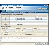
Table 3–21. Power Management Page Parameters (Part 1 of 2)
Parameter
256 ns to 8,192 ns (in
256-ns increments)
< 64 ns to > 4 μs
0 - 255
0 - 255
On/Off
< 1μs to > 64 μs
Table 3–21
Value
PCI Express Compiler Version 6.1
describes the parameters you can set on this page.
Indicate the idle threshold for L0s entry. This parameter
specifies the amount of time the link must be idle before the
transmitter transitions to L0s state. The PCI Express
specification states that this time should be no more than
7 μs, but the exact value is implementation-specific. If you
select the Stratix GX PHY or Stratix II GX PHY, this
parameter is disabled and set to its maximum value If you
are using an external PHY; consult the PHY vendor's
documentation to determine the correct value for this
parameter.
Indicate the acceptable endpoint L0s latency for the device
capabilities register. Sets the read-only value of the endpoint
L0s acceptable latency field of the device capabilities
register. This value should be based on how much latency
the application layer can tolerate.
Indicate the number of fast training sequences needed in
common clock mode. The number of fast training sequences
required is transmitted to the other end of the link during link
initialization and is also used to calculate the L0s exit latency
field of the device capabilities register. If you select the
Stratix GX PHY or Stratix II GX PHY, this parameter is
disabled and set to its maximum value. If you are using an
external PHY, consult the PHY vendor's documentation to
determine the correct value for this parameter.
Indicate the number of fast training sequences needed in
separate clock mode. The number of fast training sequences
required is transmitted to the other end of the link during link
initialization and is also used to calculate the L0s exit latency
field of the device capabilities register. If you select the
Stratix GX PHY or Stratix II GX PHY, this parameter is
disabled and set to its maximum value. If you are using an
external PHY, consult the PHY vendor's documentation to
determine the correct value for this parameter.
Set the L1 active state power management support bit in the
link capabilities register. If you select the Stratix GX PHY or
Stratix II GX PHY, this option is turned off and disabled.
Indicate the endpoint L1 acceptable latency. Sets the read-
only value of the endpoint L1 acceptable latency field of the
device capabilities register. This value should be based on
how much latency the application layer can tolerate.
Description
Altera Corporation
December 2006
Related parts for IPR-PCIE/8
Image
Part Number
Description
Manufacturer
Datasheet
Request
R

Part Number:
Description:
IP CORE Renewal Of IP-PCI/MT32
Manufacturer:
Altera
Datasheet:
Part Number:
Description:
IP CORE Renewal Of IP-PCI/MT64
Manufacturer:
Altera
Datasheet:
Part Number:
Description:
IP CORE Renewal Of IP-PCI/T32
Manufacturer:
Altera
Datasheet:
Part Number:
Description:
IP CORE Renewal Of IP-PCI/T64
Manufacturer:
Altera
Datasheet:

Part Number:
Description:
IP CORE Renewal Of IP-PCIE/1
Manufacturer:
Altera
Datasheet:
Part Number:
Description:
IP CORE Renewal Of IP-PCIE/4
Manufacturer:
Altera
Datasheet:
Part Number:
Description:
IP NIOS II MEGACORE RENEW
Manufacturer:
Altera
Datasheet:
Part Number:
Description:
IP CORE Renewal Of IP-XAUIPCS
Manufacturer:
Altera
Datasheet:

Part Number:
Description:
CPLD, EP610 Family, ECMOS Process, 300 Gates, 16 Macro Cells, 16 Reg., 16 User I/Os, 5V Supply, 35 Speed Grade, 24DIP
Manufacturer:
Altera Corporation
Datasheet:
Part Number:
Description:
CPLD, EP610 Family, ECMOS Process, 300 Gates, 16 Macro Cells, 16 Reg., 16 User I/Os, 5V Supply, 15 Speed Grade, 24DIP
Manufacturer:
Altera Corporation
Datasheet:
Part Number:
Description:
Manufacturer:
Altera Corporation
Datasheet: