DF71251AD50FPV Renesas Electronics America, DF71251AD50FPV Datasheet - Page 56
DF71251AD50FPV
Manufacturer Part Number
DF71251AD50FPV
Description
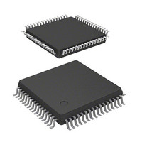
MCU RISC FLASH 32K 8K 64LQFP
Manufacturer
Renesas Electronics America
Series
SuperH® SH Tinyr
Datasheet
1.DF71243N50FPV.pdf
(794 pages)
Specifications of DF71251AD50FPV
Core Processor
SH-2
Core Size
32-Bit
Speed
50MHz
Connectivity
SCI
Peripherals
POR, PWM, WDT
Number Of I /o
37
Program Memory Size
32KB (32K x 8)
Program Memory Type
FLASH
Ram Size
8K x 8
Voltage - Supply (vcc/vdd)
4 V ~ 5.5 V
Data Converters
A/D 8x10b
Oscillator Type
External
Operating Temperature
-40°C ~ 85°C
Package / Case
64-LQFP
Lead Free Status / RoHS Status
Lead free / RoHS Compliant
Eeprom Size
-
Available stocks
Company
Part Number
Manufacturer
Quantity
Price
Company:

Part Number:
DF71251AD50FPV
Manufacturer:
Renesas Electronics America
Quantity:
10 000


The instruction code, operation, and execution cycles of the instructions are listed in the following
tables, classified by type.
Notes: 1. The table shows the minimum number of execution states. In practice, the number of
Rev. 5.00 Mar. 06, 2009 Page 36 of 770
REJ09B0243-0500
Instruction
Indicated by mnemonic.
Explanation of Symbols
OP.Sz SRC, DEST
Rm: Source register
Rn: Destination
register
imm: Immediate data
disp: Displacement*
OP:
Sz:
SRC: Source
DEST: Destination
Operation code
Size
2.
•
•
instruction execution states will be increased in cases such as the following:
Scaled (×1, ×2, or ×4) according to the instruction operand size, etc.
For details, see SH-1/SH-2/SH-DSP Software Manual.
When there is contention between an instruction fetch and a data access
When the destination register of a load instruction (memory → register) is also used
by the following instruction
2
Instruction Code
Indicated in MSB ↔
LSB order.
Explanation of Symbols
mmmm: Source register
nnnn: Destination
register
iiii:
dddd: Displacement
0000: R0
0001: R1
.........
1111: R15
Immediate data
Summary of
Operation
Indicates summary of
operation.
Explanation of Symbols
→, ←:
(xx):
M/Q/T: Flag bits in SR
&:
|:
^:
–:
<<n: n-bit left shift
>>n: n-bit right shift
Logical AND of each bit
Logical OR of each bit
Exclusive logical OR of
each bit
Logical NOT of each bit
Transfer direction
Memory operand
Execution
Cycles
Value when no
wait cycles are
inserted *
1
T Bit
Value of T bit after
instruction is executed
Explanation of Symbols
⎯: No change
Related parts for DF71251AD50FPV
Image
Part Number
Description
Manufacturer
Datasheet
Request
R

Part Number:
Description:
KIT STARTER FOR M16C/29
Manufacturer:
Renesas Electronics America
Datasheet:

Part Number:
Description:
KIT STARTER FOR R8C/2D
Manufacturer:
Renesas Electronics America
Datasheet:

Part Number:
Description:
R0K33062P STARTER KIT
Manufacturer:
Renesas Electronics America
Datasheet:

Part Number:
Description:
KIT STARTER FOR R8C/23 E8A
Manufacturer:
Renesas Electronics America
Datasheet:

Part Number:
Description:
KIT STARTER FOR R8C/25
Manufacturer:
Renesas Electronics America
Datasheet:

Part Number:
Description:
KIT STARTER H8S2456 SHARPE DSPLY
Manufacturer:
Renesas Electronics America
Datasheet:

Part Number:
Description:
KIT STARTER FOR R8C38C
Manufacturer:
Renesas Electronics America
Datasheet:

Part Number:
Description:
KIT STARTER FOR R8C35C
Manufacturer:
Renesas Electronics America
Datasheet:

Part Number:
Description:
KIT STARTER FOR R8CL3AC+LCD APPS
Manufacturer:
Renesas Electronics America
Datasheet:
Part Number:
Description:
KIT STARTER FOR RX610
Manufacturer:
Renesas Electronics America
Datasheet:

Part Number:
Description:
KIT STARTER FOR R32C/118
Manufacturer:
Renesas Electronics America
Datasheet:

Part Number:
Description:
KIT DEV RSK-R8C/26-29
Manufacturer:
Renesas Electronics America
Datasheet:

Part Number:
Description:
KIT STARTER FOR SH7124
Manufacturer:
Renesas Electronics America
Datasheet:

Part Number:
Description:
KIT STARTER FOR H8SX/1622
Manufacturer:
Renesas Electronics America
Datasheet:

Part Number:
Description:
KIT DEV FOR SH7203
Manufacturer:
Renesas Electronics America
Datasheet: