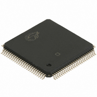
CY7C67300-100AXA Cypress Semiconductor Corp, CY7C67300-100AXA Datasheet - Page 9

CY7C67300-100AXA
Manufacturer Part Number
CY7C67300-100AXA
Description
IC,Peripheral (Multifunction) Controller,QFP,100PIN
Manufacturer
Cypress Semiconductor Corp
Series
EZ-Host™r
Datasheet
1.CY7C67300-100AXA.pdf
(98 pages)
Specifications of CY7C67300-100AXA
Applications
USB Host/Peripheral Controller
Core Processor
CY16
Program Memory Type
ROM (8 kB)
Controller Series
CY7C673xx
Ram Size
16K x 8
Interface
SPI Serial, USB, HPI
Number Of I /o
32
Voltage - Supply
3 V ~ 3.6 V
Operating Temperature
-40°C ~ 85°C
Mounting Type
Surface Mount
Package / Case
100-LQFP
Lead Free Status / RoHS Status
Lead free / RoHS Compliant
For Use With
CY4640 - KIT MASS STORAGE REF DESIGNCY3663 - KIT DEV EZ-OTG/EZ-HOST
Lead Free Status / RoHS Status
Lead free / RoHS Compliant
Available stocks
Company
Part Number
Manufacturer
Quantity
Price
Company:
Part Number:
CY7C67300-100AXA
Manufacturer:
Cypress Semiconductor Corp
Quantity:
10 000
Company:
Part Number:
CY7C67300-100AXAT
Manufacturer:
Cypress Semiconductor Corp
Quantity:
10 000
Document #: 38-08015 Rev. *G
Programmable Pulse/PWM Interface
EZ-Host has four built-in PWM output channels. Each channel
provides a programmable timing generator sequence that can
be used to interface to various image sensors or other appli-
cations. The PWM interface is exposed through GPIO pins.
Programmable Pulse/PWM Features
Programmable Pulse/PWM Pins.
Table 11.PWM Interface Pins
Host Port Interface
EZ-Host has an HPI interface. The HPI interface provides
DMA access to the EZ-Host internal memory by an external
host, plus a bidirectional mailbox register for supporting
high-level communication protocols. This port is designed to
be the primary high-speed connection to a host processor.
Complete control of EZ-Host can be accomplished through
this interface via an extensible API and communication
protocol. Other than the HW communication protocols, a host
processor has identical control over EZ-Host whether
connecting to the HPI or HSS port. The HPI interface is
exposed through GPIO pins.
HPI Features
Notes
3. HPI_INT is for the Outgoing Mailbox Interrupt.
4. HPI strobes are negative logic sampled on rising edge.
• Four independent programmable waveform generators
• Programmable predefined frequencies ranging from 5.90
• Configurable polarity
• Continuous and one-shot mode available
• 16-bit data bus interface
• 16 MB/s throughput
• Auto-Increment of address pointer for fast block mode
• Direct memory access (DMA) to internal memory
• Bidirectional Mailbox register
• Byte Swapping
• Complete access to internal memory
• Complete control of SIEs through HPI
• Dedicated HPI Status Register
KHz to 48 MHz
transfers
Pin Name
PWM3
PWM2
PWM1
PWM0
Pin Number
44
53
54
55
HPI Pins.
Table 12.HPI Interface Pins
The two HPI address pins are used to address one of four
possible HPI port registers as shown in
Table 13.HPI Addressing
HPI Address
HPI Mailbox
HPI A[1:0]
HPI Status
Pin Name
HPI Data
nWR
nRD
nCS
D15
D14
D13
D12
D11
D10
INT
A1
A0
D9
D8
D7
D6
D5
D4
D3
D2
D1
D0
[3, 4]
A1
0
0
1
1
Pin Number
46
47
48
49
50
52
56
57
58
59
60
61
65
66
86
87
89
90
91
92
93
94
Table
CY7C67300
A0
0
1
0
1
13.
Page 9 of 98
[+] Feedback


