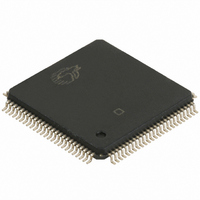
CY7C67300-100AXA Cypress Semiconductor Corp, CY7C67300-100AXA Datasheet - Page 65

CY7C67300-100AXA
Manufacturer Part Number
CY7C67300-100AXA
Description
IC,Peripheral (Multifunction) Controller,QFP,100PIN
Manufacturer
Cypress Semiconductor Corp
Series
EZ-Host™r
Datasheet
1.CY7C67300-100AXA.pdf
(98 pages)
Specifications of CY7C67300-100AXA
Applications
USB Host/Peripheral Controller
Core Processor
CY16
Program Memory Type
ROM (8 kB)
Controller Series
CY7C673xx
Ram Size
16K x 8
Interface
SPI Serial, USB, HPI
Number Of I /o
32
Voltage - Supply
3 V ~ 3.6 V
Operating Temperature
-40°C ~ 85°C
Mounting Type
Surface Mount
Package / Case
100-LQFP
Lead Free Status / RoHS Status
Lead free / RoHS Compliant
For Use With
CY4640 - KIT MASS STORAGE REF DESIGNCY3663 - KIT DEV EZ-OTG/EZ-HOST
Lead Free Status / RoHS Status
Lead free / RoHS Compliant
Available stocks
Company
Part Number
Manufacturer
Quantity
Price
Company:
Part Number:
CY7C67300-100AXA
Manufacturer:
Cypress Semiconductor Corp
Quantity:
10 000
Company:
Part Number:
CY7C67300-100AXAT
Manufacturer:
Cypress Semiconductor Corp
Quantity:
10 000
Document #: 38-08015 Rev. *G
mode this read-only bit indicates if an any of the endpoint inter-
rupts occur on Device 2. Firmware will need to determine
which endpoint interrupt occurred.
1: Interrupt triggered
0: Interrupt did not trigger
Done1 Flag (Bit 2)
In host mode the Done 1 Flag bit is a read-only bit that
indicates if a host packet done interrupt occurs on Host 1. In
device mode this read-only bit indicates if an any of the
endpoint interrupts occur on Device 1. Firmware will need to
determine which endpoint interrupt occurred.
1: Interrupt triggered
0: Interrupt did not trigger
SPI Registers
There are twelve registers dedicated to SPI operation. Each of these registers is covered in this section and summarized in
Table
Table 44.SPI Registers
SPI Configuration Register [0xC0C8] [R/W]
Register Description
The SPI Configuration Register controls the SPI port. Fields apply to both master and slave mode unless otherwise noted.
SPI Configuration Register
SPI Control Register
SPI Interrupt Enable Register
SPI Status Register
SPI Interrupt Clear Register
SPI CRC Control Register
SPI CRC Value
SPI Data Register
SPI Transmit Address Register
SPI Transmit Count Register
SPI Receive Address Register
SPI Receive Count Register
Bit #
Field
Read/Write
Default
Bit #
Field
Read/Write
Default
44.
Enable
Master
Enable
Active
3Wire
R/W
15
R
1
7
0
Register Name
Master
Enable
Phase
Select
R/W
R/W
14
0
6
0
Figure 71. SPI Configuration Register
SCK Polarity
Enable
Select
R/W
R/W
SS
13
0
5
0
R/W
R/W
12
4
1
0
Reset1 Flag (Bit 1)
The Reset1 Flag bit is a read-only bit that indicates if a USB
Reset interrupt occurs on either Host/Device 1.
1: Interrupt triggered
0: Interrupt did not trigger
Mailbox Out Flag (Bit 0)
The Mailbox Out Flag bit is a read-only bit that indicates if a
message is ready in the outgoing mailbox. This interrupt clears
when the external host reads from the HPI Mailbox Register.
1: Interrupt triggered
0: Interrupt did not trigger
0xC0C8
0xC0CA
0xC0CC
0xC0CE
0xC0D0
0xC0D2
0xC0D4
0xC0D6
0xC0D8
0xC0DA
0xC0DC
0xC0DE
R/W
R/W
11
3
1
0
Scale Select
Address
SS Delay Select
R/W
R/W
10
2
1
0
R/W
R/W
R/W
R
W
R/W
R/W
R/W
R/W
R/W
R/W
R/W
R/W
R/W
1
1
9
0
CY7C67300
Page 65 of 98
R/W
Reserved
R/W
0
1
8
0
-
[+] Feedback


