YLCDRSK2378 Renesas Electronics America, YLCDRSK2378 Datasheet - Page 918
YLCDRSK2378
Manufacturer Part Number
YLCDRSK2378
Description
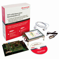
KIT DEV EVAL H8S/2378 LCD
Manufacturer
Renesas Electronics America
Series
H8®r
Datasheet
1.YR0K42378FC000BA.pdf
(1208 pages)
Specifications of YLCDRSK2378
Main Purpose
Displays, LCD Controller
Embedded
Yes, MCU, 16-Bit
Utilized Ic / Part
YLCDRSK2378
Primary Attributes
5.7" QVGA, Touch Screen
Secondary Attributes
Source Code on CD, Debugging Requires Emulator Cable E10A USB/JTAG
Lead Free Status / RoHS Status
Lead free / RoHS Compliant


Section 20 Flash Memory (0.35-μm F-ZTAT Version)
20.7
A software method, using the CPU, is employed to program and erase flash memory in the on-
board programming modes. Depending on the FLMCR1 and FLMCR2 setting, the flash memory
operates in one of the following four modes: program mode, erase mode, program-verify mode,
and erase-verify mode. The programming control program in boot mode and the user
program/erase program in user mode use these operating modes in combination to perform
programming/erasing. Flash memory programming and erasing should be performed in
accordance with the descriptions in section 20.7.1, Program/Program-Verify and section 20.7.2,
Erase/Erase-Verify, respectively.
20.7.1
When programming data or programs to the flash memory, the program/program-verify flowchart
shown in figure 20.7 should be followed. Performing programming operations according to this
flowchart will enable data or programs to be programmed to the flash memory without subjecting
the chip to voltage stress or sacrificing program data reliability.
1. Programming must be done to an empty address. Do not reprogram an address to which
2. Programming should be carried out 128 bytes at a time. A 128-byte data transfer must be
3. Prepare the following data storage areas in RAM: a 128-byte programming data area, a 128-
4. Consecutively transfer 128 bytes of data in byte units from the programming data area,
5. The time during which the P bit is set to 1 is the programming time. Figure 20.7 shows the
6. The watchdog timer (WDT) is set to prevent overprogramming due to program runaway, etc.
7. For a dummy write to a verify address, write 1-byte data H'FF to an address whose lower 2 bits
8. The maximum number of repetitions of the program/program-verify sequence to the same bit
Rev.7.00 Mar. 18, 2009 page 850 of 1136
REJ09B0109-0700
programming has already been performed.
performed even if programming fewer than 128 bytes. In this case, H'FF data must be written
to the extra addresses.
byte reprogramming data area, and a 128-byte additional-programming data area. Perform
reprogramming data computation and additional programming data computation according to
figure 20.9.
reprogramming data area, or additional-programming data area to the flash memory. The
program address and 128-byte data are latched in the flash memory. The lower 8 bits of the
start address in the flash memory destination area must be H'00 or H'80.
allowable programming times.
Set a value greater than (y + z2 + α + β) µs as the WDT overflow period.
are B'00. Verify data can be read in words from the address to which a dummy write was
performed.
(N) must not be exceeded.
Flash Memory Programming/Erasing
Program/Program-Verify
Related parts for YLCDRSK2378
Image
Part Number
Description
Manufacturer
Datasheet
Request
R

Part Number:
Description:
KIT STARTER FOR M16C/29
Manufacturer:
Renesas Electronics America
Datasheet:

Part Number:
Description:
KIT STARTER FOR R8C/2D
Manufacturer:
Renesas Electronics America
Datasheet:

Part Number:
Description:
R0K33062P STARTER KIT
Manufacturer:
Renesas Electronics America
Datasheet:

Part Number:
Description:
KIT STARTER FOR R8C/23 E8A
Manufacturer:
Renesas Electronics America
Datasheet:

Part Number:
Description:
KIT STARTER FOR R8C/25
Manufacturer:
Renesas Electronics America
Datasheet:

Part Number:
Description:
KIT STARTER H8S2456 SHARPE DSPLY
Manufacturer:
Renesas Electronics America
Datasheet:

Part Number:
Description:
KIT STARTER FOR R8C38C
Manufacturer:
Renesas Electronics America
Datasheet:

Part Number:
Description:
KIT STARTER FOR R8C35C
Manufacturer:
Renesas Electronics America
Datasheet:

Part Number:
Description:
KIT STARTER FOR R8CL3AC+LCD APPS
Manufacturer:
Renesas Electronics America
Datasheet:
Part Number:
Description:
KIT STARTER FOR RX610
Manufacturer:
Renesas Electronics America
Datasheet:

Part Number:
Description:
KIT STARTER FOR R32C/118
Manufacturer:
Renesas Electronics America
Datasheet:

Part Number:
Description:
KIT DEV RSK-R8C/26-29
Manufacturer:
Renesas Electronics America
Datasheet:

Part Number:
Description:
KIT STARTER FOR SH7124
Manufacturer:
Renesas Electronics America
Datasheet:

Part Number:
Description:
KIT STARTER FOR H8SX/1622
Manufacturer:
Renesas Electronics America
Datasheet:

Part Number:
Description:
KIT DEV FOR SH7203
Manufacturer:
Renesas Electronics America
Datasheet: