YLCDRSK2378 Renesas Electronics America, YLCDRSK2378 Datasheet - Page 1045
YLCDRSK2378
Manufacturer Part Number
YLCDRSK2378
Description
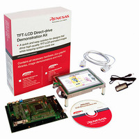
KIT DEV EVAL H8S/2378 LCD
Manufacturer
Renesas Electronics America
Series
H8®r
Datasheet
1.YR0K42378FC000BA.pdf
(1208 pages)
Specifications of YLCDRSK2378
Main Purpose
Displays, LCD Controller
Embedded
Yes, MCU, 16-Bit
Utilized Ic / Part
YLCDRSK2378
Primary Attributes
5.7" QVGA, Touch Screen
Secondary Attributes
Source Code on CD, Debugging Requires Emulator Cable E10A USB/JTAG
Lead Free Status / RoHS Status
Lead free / RoHS Compliant


Clearing Hardware Standby Mode: Hardware standby mode is cleared by means of the STBY
pin and the RES pin. When the STBY pin is driven high while the RES pin is low, the reset state is
set and clock oscillation is started. Ensure that the RES pin is held low until the clock oscillator
stabilizes (for details on the oscillation stabilization time, refer to table 24.2). When the RES pin is
subsequently driven high, a transition is made to the program execution state via the reset
exception handling state.
Hardware Standby Mode Timing: Figure 24.3 shows an example of hardware standby mode
timing.
When the STBY pin is driven low after the RES pin has been driven low, a transition is made to
hardware standby mode. Hardware standby mode is cleared by driving the STBY pin high,
waiting for the oscillation stabilization time, then changing the RES pin from low to high.
Hardware Standby Mode Timing when Power Is Supplied (Only H8S/2378 0.18μm F-ZTAT
Group and H8S/2378R 0.18μm F-ZTAT Group): When entering hardware standby mode
immediately after the power is supplied, the RES signal must be driven low for a given period
with retaining the STBY signal high. After the RES signal is canceled, drive the STBY signal low.
Oscillator
RES
STBY
Figure 24.3 Hardware Standby Mode Timing
Rev.7.00 Mar. 18, 2009 page 977 of 1136
stabilization
Oscillation
Section 24 Power-Down Modes
time
REJ09B0109-0700
exception
handling
Reset
Related parts for YLCDRSK2378
Image
Part Number
Description
Manufacturer
Datasheet
Request
R

Part Number:
Description:
KIT STARTER FOR M16C/29
Manufacturer:
Renesas Electronics America
Datasheet:

Part Number:
Description:
KIT STARTER FOR R8C/2D
Manufacturer:
Renesas Electronics America
Datasheet:

Part Number:
Description:
R0K33062P STARTER KIT
Manufacturer:
Renesas Electronics America
Datasheet:

Part Number:
Description:
KIT STARTER FOR R8C/23 E8A
Manufacturer:
Renesas Electronics America
Datasheet:

Part Number:
Description:
KIT STARTER FOR R8C/25
Manufacturer:
Renesas Electronics America
Datasheet:

Part Number:
Description:
KIT STARTER H8S2456 SHARPE DSPLY
Manufacturer:
Renesas Electronics America
Datasheet:

Part Number:
Description:
KIT STARTER FOR R8C38C
Manufacturer:
Renesas Electronics America
Datasheet:

Part Number:
Description:
KIT STARTER FOR R8C35C
Manufacturer:
Renesas Electronics America
Datasheet:

Part Number:
Description:
KIT STARTER FOR R8CL3AC+LCD APPS
Manufacturer:
Renesas Electronics America
Datasheet:
Part Number:
Description:
KIT STARTER FOR RX610
Manufacturer:
Renesas Electronics America
Datasheet:

Part Number:
Description:
KIT STARTER FOR R32C/118
Manufacturer:
Renesas Electronics America
Datasheet:

Part Number:
Description:
KIT DEV RSK-R8C/26-29
Manufacturer:
Renesas Electronics America
Datasheet:

Part Number:
Description:
KIT STARTER FOR SH7124
Manufacturer:
Renesas Electronics America
Datasheet:

Part Number:
Description:
KIT STARTER FOR H8SX/1622
Manufacturer:
Renesas Electronics America
Datasheet:

Part Number:
Description:
KIT DEV FOR SH7203
Manufacturer:
Renesas Electronics America
Datasheet: