YLCDRSK2378 Renesas Electronics America, YLCDRSK2378 Datasheet - Page 161
YLCDRSK2378
Manufacturer Part Number
YLCDRSK2378
Description
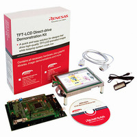
KIT DEV EVAL H8S/2378 LCD
Manufacturer
Renesas Electronics America
Series
H8®r
Datasheet
1.YR0K42378FC000BA.pdf
(1208 pages)
Specifications of YLCDRSK2378
Main Purpose
Displays, LCD Controller
Embedded
Yes, MCU, 16-Bit
Utilized Ic / Part
YLCDRSK2378
Primary Attributes
5.7" QVGA, Touch Screen
Secondary Attributes
Source Code on CD, Debugging Requires Emulator Cable E10A USB/JTAG
Lead Free Status / RoHS Status
Lead free / RoHS Compliant


4.1
As table 4.1 indicates, exception handling may be caused by a reset, trace, interrupt, or trap
instruction. Exception handling is prioritized as shown in table 4.1. If two or more exceptions
occur simultaneously, they are accepted and processed in order of priority. Exception sources, the
stack structure, and operation of the CPU vary depending on the interrupt control mode. For
details on the interrupt control mode, refer to section 5, Interrupt Controller.
Table 4.1
Priority
High
Low
Notes: 1. Traces are enabled only in interrupt control mode 2. Trace exception handling is not
4.2
Different vector addresses are assigned to different exception sources. Table 4.2 lists the exception
sources and their vector addresses. Since the usable modes differ depending on the product, for
details on each product, refer to section 3, MCU Operating Modes.
2. Not available in this LSI.
3. Interrupt detection is not performed on completion of ANDC, ORC, XORC, or LDC
4. Trap instruction exception handling requests are accepted at all times in program
Exception Handling Types and Priority
Exception Sources and Exception Vector Table
Exception Type
Reset
Trace *
Direct transition *
Interrupt
Trap instruction *
executed after execution of an RTE instruction.
instruction execution, or on completion of reset exception handling.
execution state.
Exception Types and Priority
1
Section 4 Exception Handling
4
2
Start of Exception Handling
Starts immediately after a low-to-high transition at the RES
pin, or when the watchdog timer overflows. The CPU enters
the reset state when the RES pin is low.
Starts when execution of the current instruction or exception
handling ends, if the trace (T) bit in the EXR is set to 1.
Starts when the direct transition occurs by execution of the
SLEEP instruction.
Starts when execution of the current instruction or exception
handling ends, if an interrupt request has been issued. *
Started by execution of a trap instruction (TRAPA)
Rev.7.00 Mar. 18, 2009 page 93 of 1136
Section 4 Exception Handling
REJ09B0109-0700
3
Related parts for YLCDRSK2378
Image
Part Number
Description
Manufacturer
Datasheet
Request
R

Part Number:
Description:
KIT STARTER FOR M16C/29
Manufacturer:
Renesas Electronics America
Datasheet:

Part Number:
Description:
KIT STARTER FOR R8C/2D
Manufacturer:
Renesas Electronics America
Datasheet:

Part Number:
Description:
R0K33062P STARTER KIT
Manufacturer:
Renesas Electronics America
Datasheet:

Part Number:
Description:
KIT STARTER FOR R8C/23 E8A
Manufacturer:
Renesas Electronics America
Datasheet:

Part Number:
Description:
KIT STARTER FOR R8C/25
Manufacturer:
Renesas Electronics America
Datasheet:

Part Number:
Description:
KIT STARTER H8S2456 SHARPE DSPLY
Manufacturer:
Renesas Electronics America
Datasheet:

Part Number:
Description:
KIT STARTER FOR R8C38C
Manufacturer:
Renesas Electronics America
Datasheet:

Part Number:
Description:
KIT STARTER FOR R8C35C
Manufacturer:
Renesas Electronics America
Datasheet:

Part Number:
Description:
KIT STARTER FOR R8CL3AC+LCD APPS
Manufacturer:
Renesas Electronics America
Datasheet:
Part Number:
Description:
KIT STARTER FOR RX610
Manufacturer:
Renesas Electronics America
Datasheet:

Part Number:
Description:
KIT STARTER FOR R32C/118
Manufacturer:
Renesas Electronics America
Datasheet:

Part Number:
Description:
KIT DEV RSK-R8C/26-29
Manufacturer:
Renesas Electronics America
Datasheet:

Part Number:
Description:
KIT STARTER FOR SH7124
Manufacturer:
Renesas Electronics America
Datasheet:

Part Number:
Description:
KIT STARTER FOR H8SX/1622
Manufacturer:
Renesas Electronics America
Datasheet:

Part Number:
Description:
KIT DEV FOR SH7203
Manufacturer:
Renesas Electronics America
Datasheet: