8.10.00 J-TRACE ARM Segger Microcontroller Systems, 8.10.00 J-TRACE ARM Datasheet - Page 98
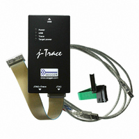
8.10.00 J-TRACE ARM
Manufacturer Part Number
8.10.00 J-TRACE ARM
Description
JTAG EMULATOR ARM7/ARM9 ETM
Manufacturer
Segger Microcontroller Systems
Type
Emulatorr
Specifications of 8.10.00 J-TRACE ARM
Contents
Emulation Module
For Use With/related Products
ARM7, ARM9
Lead Free Status / RoHS Status
Lead free / RoHS Compliant
Other names
899-1006


98
5.3
5.3.1
5.3.1.1 Configuration
5.3.2
J-Link / J-Trace (UM08001)
By default, only one ARM device is assumed to be in the JTAG scan chain. If you have
multiple devices in the scan chain, you must properly configure it. To do so, you have
to specify the exact position of the ARM device that should be addressed. Configuration of
the scan is done by the target application. A target application can be a debugger
such as the IAR C-SPY® debugger, ARM’s AXD using RDI, a flash programming appli-
cation such as SEGGER’s J-Flash, or any other application using J-Link / J-Trace. It is
the application’s responsibility to supply a way to configure the scan chain. Most
applications offer a dialog box for this purpose.
J-Link / J-Trace can handle multiple devices in the scan chain. This applies to hard-
ware where multiple chips are connected to the same JTAG connector. As can be seen
in the following figure, the TCK and TMS lines of all JTAG device are connected, while
the TDI and TDO lines form a bus.
Currently, up to 8 devices in the scan chain are supported. One or more of these
devices can be ARM cores; the other devices can be of any other type but need to
comply with the JTAG standard.
The configuration of the scan chain depends on the application used. Read JTAG
interface on page 98 for further instructions and configuration examples.
As explained before, it is responsibility of the application to allow the user to config-
ure the scan chain. This is typically done in a dialog box; some sample dialog boxes
are shown below.
JTAG interface
Multiple devices in the scan chain
Sample configuration dialog boxes
TDI
Device 1
TDI
TDO
CHAPTER 5
JTAG
© 2004-2011 SEGGER Microcontroller GmbH & Co. KG
TDI
Device 0
TDO
Working with J-Link and J-Trace
TDO
Related parts for 8.10.00 J-TRACE ARM
Image
Part Number
Description
Manufacturer
Datasheet
Request
R

Part Number:
Description:
CONNECTOR JTAG-ARM ISOLATION
Manufacturer:
Segger Microcontroller Systems
Datasheet:

Part Number:
Description:
ADAPTER ARM TARGET 14PIN RIBBON
Manufacturer:
Segger Microcontroller Systems
Datasheet:

Part Number:
Description:
JTAG EMULATOR FOR ARM CORES
Manufacturer:
Segger Microcontroller Systems
Datasheet:

Part Number:
Description:
JTAG EMULATOR FOR ARM CORES
Manufacturer:
Segger Microcontroller Systems
Datasheet:

Part Number:
Description:
PROGRAMMING TOOL FOR MCU
Manufacturer:
Segger Microcontroller Systems
Datasheet:

Part Number:
Description:
PROGRAMMING TOOL FOR ST7 MCU
Manufacturer:
Segger Microcontroller Systems
Datasheet:

Part Number:
Description:
PROGRAMMING TOOL FOR STM8
Manufacturer:
Segger Microcontroller Systems
Datasheet:

Part Number:
Description:
PROGRAMMER JTAG FOR ARM CORES
Manufacturer:
Segger Microcontroller Systems
Datasheet:

Part Number:
Description:
JTAG EMULATOR USB ETHERNET ARM
Manufacturer:
Segger Microcontroller Systems
Datasheet:

Part Number:
Description:
EMULATOR JTAG/SWD CORTEX M3
Manufacturer:
Segger Microcontroller Systems
Datasheet: