8.10.00 J-TRACE ARM Segger Microcontroller Systems, 8.10.00 J-TRACE ARM Datasheet - Page 119
8.10.00 J-TRACE ARM
Manufacturer Part Number
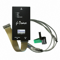
8.10.00 J-TRACE ARM
Description
JTAG EMULATOR ARM7/ARM9 ETM
Manufacturer
Segger Microcontroller Systems
Type
Emulatorr
Specifications of 8.10.00 J-TRACE ARM
Contents
Emulation Module
For Use With/related Products
ARM7, ARM9
Lead Free Status / RoHS Status
Lead free / RoHS Compliant
Other names
899-1006


5.8.1.4 Type 3: No reset
5.8.1.5 Type 4: Hardware, halt with WP
5.8.1.6 Type 5: Hardware, halt with DBGRQ
5.8.1.7 Type 6: Software
5.8.1.8 Type 7: Reserved
5.8.1.9 Type 8: Software, for ATMEL AT91SAM7 MCUs
5.8.1.10 Type 9: Hardware, for NXP LPC MCUs
J-Link / J-Trace (UM08001)
No reset is performed. Nothing happens.
The hardware RESET pin is used to reset the CPU. After reset release, J-Link continu-
ously tries to halt the CPU using a watchpoint. This typically halts the CPU shortly
after reset release; the CPU can in most systems execute some instructions before it
is halted.
The number of instructions executed depends primarily on the JTAG speed: the
higher the JTAG speed, the faster the CPU can be halted. Some CPUs can actually be
halted before executing any instruction, because the start of the CPU is delayed after
reset release
The hardware RESET pin is used to reset the CPU. After reset release, J-Link continu-
ously tries to halt the CPU using the DBGRQ. This typically halts the CPU shortly after
reset release; the CPU can in most systems execute some instructions before it is
halted.
The number of instructions executed depends primarily on the JTAG speed: the
higher the JTAG speed, the faster the CPU can be halted. Some CPUs can actually be
halted before executing any instruction, because the start of the CPU is delayed after
reset release.
This reset strategy is only a software reset. "Software reset" means basically no
reset, just changing the CPU registers such as PC and CPSR. This reset strategy sets
the CPU registers to their after-Reset values:
•
•
•
•
•
Reserved reset type.
The reset pin of the device is disabled by default. This means that the reset strate-
gies which rely on the reset pin (low pulse on reset) do not work by default. For this
reason a special reset strategy has been made available.
It is recommended to use this reset strategy. This special reset strategy resets the
peripherals by writing to the RSTC_CR register. Resetting the peripherals puts all
peripherals in the defined reset state. This includes memory mapping register, which
means that after reset flash is mapped to address 0. It is also possible to achieve the
same effect by writing 0x4 to the RSTC_CR register located at address 0xfffffd00.
After reset a bootloader is mapped at address 0 on ARM 7 LPC devices. This reset
strategy performs a reset via reset strategy Type 1 in order to reset the CPU. It also
ensures that flash is mapped to address 0 by writing the MEMMAP register of the LPC.
This reset strategy is the recommended one for all ARM 7 LPC devices.
PC = 0
CPSR = 0xD3 (Supervisor mode, ARM, IRQ / FIQ disabled)
All SPSR registers = 0x10
All other registers (which are unpredictable after reset) are set to 0.
The hardware RESET pin is not affected.
© 2004-2011 SEGGER Microcontroller GmbH & Co. KG
119
Related parts for 8.10.00 J-TRACE ARM
Image
Part Number
Description
Manufacturer
Datasheet
Request
R

Part Number:
Description:
CONNECTOR JTAG-ARM ISOLATION
Manufacturer:
Segger Microcontroller Systems
Datasheet:

Part Number:
Description:
ADAPTER ARM TARGET 14PIN RIBBON
Manufacturer:
Segger Microcontroller Systems
Datasheet:

Part Number:
Description:
JTAG EMULATOR FOR ARM CORES
Manufacturer:
Segger Microcontroller Systems
Datasheet:

Part Number:
Description:
JTAG EMULATOR FOR ARM CORES
Manufacturer:
Segger Microcontroller Systems
Datasheet:

Part Number:
Description:
PROGRAMMING TOOL FOR MCU
Manufacturer:
Segger Microcontroller Systems
Datasheet:

Part Number:
Description:
PROGRAMMING TOOL FOR ST7 MCU
Manufacturer:
Segger Microcontroller Systems
Datasheet:

Part Number:
Description:
PROGRAMMING TOOL FOR STM8
Manufacturer:
Segger Microcontroller Systems
Datasheet:

Part Number:
Description:
PROGRAMMER JTAG FOR ARM CORES
Manufacturer:
Segger Microcontroller Systems
Datasheet:

Part Number:
Description:
JTAG EMULATOR USB ETHERNET ARM
Manufacturer:
Segger Microcontroller Systems
Datasheet:

Part Number:
Description:
EMULATOR JTAG/SWD CORTEX M3
Manufacturer:
Segger Microcontroller Systems
Datasheet: