8.10.00 J-TRACE ARM Segger Microcontroller Systems, 8.10.00 J-TRACE ARM Datasheet - Page 97
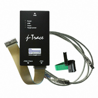
8.10.00 J-TRACE ARM
Manufacturer Part Number
8.10.00 J-TRACE ARM
Description
JTAG EMULATOR ARM7/ARM9 ETM
Manufacturer
Segger Microcontroller Systems
Type
Emulatorr
Specifications of 8.10.00 J-TRACE ARM
Contents
Emulation Module
For Use With/related Products
ARM7, ARM9
Lead Free Status / RoHS Status
Lead free / RoHS Compliant
Other names
899-1006


5.2.2
5.2.2.1 Bi-color input indicator
5.2.3
5.2.3.1 Bi-color output indicator
J-Link / J-Trace (UM08001)
Some newer J-Links such as the J-Link Pro/Ultra come with additional input/output
Indicators. The input indicator is used to give the user some information about the
status of the target hardware.
Table 5.3: J-Link bi-color input indicator
Some newer J-Links such as the J-Link Pro/Ultra come with additional input/output
Indicators. The output indicator is used to give the user some information about the
emulator-to-target connection.
Table 5.4: J-Link bi-color output indicator
GREEN
ORANGE
RED
OFF
GREEN
ORANGE
RED
Input indicator
Output indicator
Indicator status
Indicator status
Target voltage could be measured. Target is connected.
Target voltage could be measured. RESET is pulled low
(active) on target side.
RESET is pulled low (active) on target side. If no target is
connected, reset will be also active on target side.
Target power supply via Pin 19 is not active.
Target power supply via Pin 19 is active.
Target power supply via Pin 19 is active. Emulator pulls
RESET low (active).
Emulator pulls RESET low (active).
© 2004-2011 SEGGER Microcontroller GmbH & Co. KG
Meaning
Meaning
97
Related parts for 8.10.00 J-TRACE ARM
Image
Part Number
Description
Manufacturer
Datasheet
Request
R

Part Number:
Description:
CONNECTOR JTAG-ARM ISOLATION
Manufacturer:
Segger Microcontroller Systems
Datasheet:

Part Number:
Description:
ADAPTER ARM TARGET 14PIN RIBBON
Manufacturer:
Segger Microcontroller Systems
Datasheet:

Part Number:
Description:
JTAG EMULATOR FOR ARM CORES
Manufacturer:
Segger Microcontroller Systems
Datasheet:

Part Number:
Description:
JTAG EMULATOR FOR ARM CORES
Manufacturer:
Segger Microcontroller Systems
Datasheet:

Part Number:
Description:
PROGRAMMING TOOL FOR MCU
Manufacturer:
Segger Microcontroller Systems
Datasheet:

Part Number:
Description:
PROGRAMMING TOOL FOR ST7 MCU
Manufacturer:
Segger Microcontroller Systems
Datasheet:

Part Number:
Description:
PROGRAMMING TOOL FOR STM8
Manufacturer:
Segger Microcontroller Systems
Datasheet:

Part Number:
Description:
PROGRAMMER JTAG FOR ARM CORES
Manufacturer:
Segger Microcontroller Systems
Datasheet:

Part Number:
Description:
JTAG EMULATOR USB ETHERNET ARM
Manufacturer:
Segger Microcontroller Systems
Datasheet:

Part Number:
Description:
EMULATOR JTAG/SWD CORTEX M3
Manufacturer:
Segger Microcontroller Systems
Datasheet: