8.10.00 J-TRACE ARM Segger Microcontroller Systems, 8.10.00 J-TRACE ARM Datasheet
8.10.00 J-TRACE ARM
Specifications of 8.10.00 J-TRACE ARM


Related parts for 8.10.00 J-TRACE ARM


8.10.00 J-TRACE ARM Summary of contents
Page 1
J-Link / J-Trace User guide of the JTAG emulators for ARM Cores Software Version V4.24 Date: February 17, 2011 Document: UM08001 A product of SEGGER Microcontroller GmbH & Co. KG ARM Manual Rev. 0 www.segger.com ...
Page 2
Disclaimer Specifications written in this document are believed to be accurate, but are not guar- anteed to be entirely free of error. The information in this manual is subject to change for functional or performance improvements without notice. Please ...
Page 3
For further information on topics or routines not yet specified, please contact us. Revision Date V4.24 Rev. 0 110216 V4.23d 110202 V4.21g 101130 V4.21 101025 V4.20j 101019 V4.20b 100923 90 100818 89 100630 88 100622 87 100617 86 100504 85 ...
Page 4
Revision Date 81 100202 80 100104 79 091201 78 091023 77 090910 76 090828 75 090729 74 090722 73 090701 72 090618 71 090616 70 090605 J-Link / J-Trace (UM08001) By Explanation Chapter "Device Specifics" * Section "Luminary Micro" ...
Page 5
Revision Date 69 090515 68 090428 67 090402 66 090327 65 090320 64 090313 63 090212 62 090211 61 090120 60 090114 59 090108 58 090105 57 081222 56 081219 55 081218 54 081217 53 081216 J-Link / J-Trace (UM08001) ...
Page 6
Revision Date 52 081212 51 081202 50 081030 49 081029 48 080916 47 080910 46 080904 45 080902 44 080827 43 080826 42 080820 41 080811 40 080630 39 080627 38 080618 37 080617 36 080530 J-Link / J-Trace ...
Page 7
Revision Date 35 080215 34 080212 33 080207 32 0080129 SK 31 0080103 SK 30 071211 29 070912 28 070912 28 070912 27 070827 26 070710 J-Link / J-Trace (UM08001) By Explanation Chapter "J-Link and J-Trace related software" AG Section ...
Page 8
Revision Date 25 070516 24 070323 23 070320 22 070316 21 070312 20 070307 19 070226 18 070221 17 070131 16 061222 15 060914 14 060818 13 060711 12 060628 11 060607 10 060526 J-Link / J-Trace (UM08001) By ...
Page 9
Revision Date 9 060324 8 060117 7 051208 6 051118 5 051103 4 051025 3 051021 2 051011 1 050818 J-Link / J-Trace (UM08001) By Explanation Chapter "Literature and references" added. Chapter "Hardware": Added common information trace signals. OO Added ...
Page 10
J-Link / J-Trace (UM08001) © 2004-2011 SEGGER Microcontroller GmbH & Co. KG ...
Page 11
About this document This document describes J-Link and J-Trace. It provides an overview over the major features of J-Link and J-Trace, gives you some background information about JTAG, ARM and Tracing in general and describes J-Link and J-Trace related software ...
Page 12
Our most popular products are emWin, a universal graphic software package for embed- ded applications, and embOS, a small ...
Page 13
Table of Contents 1 Introduction ....................................................................................................................19 1.1 Requirements.......................................................................................... 20 1.2 Supported OS ......................................................................................... 21 1.3 J-Link / J-Trace models ............................................................................ 22 1.3.1 Model comparison.................................................................................... 23 1.3.2 J-Link ARM ............................................................................................. 24 1.3.3 J-Link Ultra ............................................................................................. 27 1.3.4 J-Link ARM Pro ........................................................................................ ...
Page 14
Installing the J-Link ARM software and documentation pack .......................... 62 3.1.1 Setup procedure ..................................................................................... 62 3.2 Setting up the USB interface..................................................................... 65 3.2.1 Verifying correct driver installation ............................................................ 65 3.3 Uninstalling the J-Link USB driver .............................................................. 67 3.4 ...
Page 15
SWD interface ....................................................................................... 103 5.4.1 SWD speed ........................................................................................... 103 5.4.2 SWO .................................................................................................... 103 5.5 Multi-core debugging ............................................................................. 105 5.5.1 How multi-core debugging works ............................................................. 105 5.5.2 Using multi-core debugging in detail ........................................................ 106 5.5.3 Things you should be aware ...
Page 16
Tracing on Kinetis K40 and K60 devices ....................................................159 7.3.3 MAC71x ................................................................................................159 7.4 Luminary Micro ......................................................................................160 7.4.1 Unlocking LM3Sxxx devices .....................................................................161 7.4.2 Stellaris LM3S100 Series .........................................................................161 7.4.3 Stellaris LM3S300 Series .........................................................................161 7.4.4 Stellaris LM3S600 Series .........................................................................161 7.4.5 Stellaris LM3S800 ...
Page 17
Designing the target board for trace ..........................................................................201 10.1 Overview of high-speed board design ....................................................... 202 10.1.1 Avoiding stubs ...................................................................................... 202 10.1.2 Minimizing Signal Skew (Balancing PCB Track Lengths)............................... 202 10.1.3 Minimizing Crosstalk .............................................................................. 202 10.1.4 Using impedance matching and ...
Page 18
J-Link / J-Trace (UM08001) © 2004-2011 SEGGER Microcontroller GmbH & Co. KG ...
Page 19
Chapter 1 Introduction This chapter gives a short overview about J-Link and J-Trace. J-Link / J-Trace (UM08001) © 2004-2011 SEGGER Microcontroller GmbH & Co ...
Page 20
Requirements Host System To use J-Link or J-Trace you need a host system running Windows 2000 or later. For a list of all operating systems which are supported by J-Link, please refer to Supported OS on page 21. ...
Page 21
Supported OS J-Link/J-Trace can be used on the following operating systems: • Microsoft Windows 2000 • Microsoft Windows XP • Microsoft Windows XP x64 • Microsoft Windows 2003 • Microsoft Windows 2003 x64 • Microsoft Windows Vista • Microsoft ...
Page 22
J-Link / J-Trace models J-Link / J-Trace is available in different variations, each designed for different pur- poses / target devices. Currently, the following models of J-Link / J-Trace are avail- able: • J-Link ARM • J-Link Ultra ...
Page 23
Model comparison The following tables show the features which are included in each J-Link / J-Trace model. Hardware features USB yes Ethernet no ARM7/9/11, Supported cores Cortex-M0/M1/ M3 JTAG yes SWD yes SWO yes ETM Trace no Software features ...
Page 24
J-Link ARM J-Link is a JTAG emulator designed for ARM cores. It connects via USB running Microsoft Windows 2000 or later. For a complete list of all operating systems which are supported, please refer to ...
Page 25
LOW level input voltage (V HIGH level input voltage (V LOW level output voltage (V load of 10 kOhm HIGH level output voltage (V load of 10 kOhm LOW level output voltage (V load of 10 kOhm HIGH level output ...
Page 26
MHz ( 4.800 MHz (n = 10) • Supports adaptive clocking. Version 5.2 Identical to version 5.0 with the following exception: • Target interface: RESET is open drain Version 5.3 Identical to version 5.2 with the ...
Page 27
J-Link Ultra J-Link Ultra is a JTAG/SWD emulator designed for ARM/Cortex and other supported CPUs fully compatible to the standard J-Link and works with the same PC software. Based on the highly optimized and proven J-Link, it ...
Page 28
Reset low level output voltage (V For the whole target voltage range (1.8V <= V LOW level input voltage (V HIGH level input voltage (V LOW level output voltage (V load of 10 kOhm HIGH level output voltage (V ...
Page 29
Serial Wire Viewer supported • Download speed up to 720 KBytes/second ** (higher download speeds will be available in the near future) • DCC speed up to 800 Kbytes/second ** • Comes with licenses for: J-Link ARM RDI, J-Link ...
Page 30
Specifications The following table gives an overview about the specifications (general, mechanical, electrical) for J-Link ARM Lite. All values are valid for J-Link ARM hardware version 8. Supported OS Electromagnetic compatibility (EMC) Operating temperature Storage temperature Relative humidity ...
Page 31
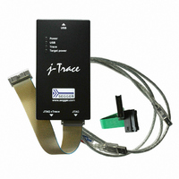
J-Trace ARM J-Trace is a JTAG emulator designed for ARM cores which includes trace (ETM) support. It connects via USB run- ning Microsoft Windows 2000 or later. For a complete list of all operating systems which ...
Page 32
Download speed The following table lists performance values (Kbytes/s) for writing to memory (RAM): Hardware J-Trace Rev. 1 Table 1.7: Download speed differences between hardware revisions All tests have been performed in the testing environment which is described ...
Page 33
J-Trace for Cortex-M3 J-Trace for Cortex- JTAG/SWD emulator designed for Cortex-M3 cores which includes trace (ETM) support. J-Trace for Cortex-M3 can also be used as a J-Link and it also supports ARM7/9 cores. Tracing on ARM7/9 targets ...
Page 34
Clock fall time ( Power supply Target interface voltage (V Voltage interface low pulse (V Voltage interface high pulse (V TRACECLK low pulse width (T TRACECLK high pulse width (T Data rise time ( Data ...
Page 35
Flasher ARM Flasher ARM is a programming tool for microcontrollers with on- chip or external Flash memory and ARM core. Flasher ARM is designed for programming flash targets with the J-Flash soft- ware or stand-alone. In addition to that ...
Page 36
Target supply current LOW level input voltage (V HIGH level input voltage (V LOW level output voltage (V load of 10 kOhm HIGH level output voltage (V load of 10 kOhm Table 1.10: Flasher ARM specifications 1.3.9 J-Link ColdFire ...
Page 37
Common features of the J-Link product family • USB 2.0 interface (Full-Speed/Hi-Speed, depends on J-Link model) • Any ARM7/9/11 (including thumb mode), Cortex-M0/M1/M3 core supported • Automatic core recognition • Maximum JTAG speed 12/25 MHz (depends on J-Link model) ...
Page 38
Supported CPU cores J-Link / J-Trace has been tested with the following cores, but should work with any ARM7/9/11, Cortex-M0/M1/M3/M4 and Cortex-A5/A8/R4 core. If you experience problems with a particular core, do not hesitate to contact Segger. • ...
Page 39
Built-in intelligence for supported CPU-cores In general, there are two ways two ways to support a CPU-core in the J-Link soft- ware: 1. Intelligence in the J-Link firmware 2. Intelligence on the PC-side (DLL) Having the intelligence in the ...
Page 40
Limitations of PC-side implementations • Instability, especially on slow targets Due to the fact that a lot of USB transactions would cause a very bad perfor- mance of J-Link, on PC-side implementations the assumption is made that the ...
Page 41
Firmware intelligence per model There are different models of J-Link / J-Trace which have built-in intelligence for dif- ferent CPU-cores. In the following, we will give you an overview about which model of J-Link / J-Trace has intelligence for ...
Page 42
Older models The table below lists the firmware CPU support for older J-Link & J-Trace models which are not sold anymore. J-Link / J-Trace model J-Link J-Link J-Link J-Link J-Link J-Link Pro J-Trace for Cortex-M 1 Table 1.12: ...
Page 43
Supported IDEs J-Link / J-Trace can be used with different IDEs. Some IDEs support J-Link directly, for other ones additional software (such as J-Link RDI) is necessary in order to use J- Link. The following tables list which features ...
Page 44
J-Link / J-Trace (UM08001) CHAPTER 1 © 2004-2011 SEGGER Microcontroller GmbH & Co. KG Introduction ...
Page 45
Chapter 2 Licensing This chapter describes the different license types of J-Link related software and the legal use of the J-Link software with original SEGGER and OEM products. J-Link / J-Trace (UM08001) © 2004-2011 SEGGER Microcontroller GmbH & Co. KG ...
Page 46
Introduction J-Link functionality can be enhanced by the features J-Flash, RDI, flash download and flash breakpoints (FlashBP). The flash breakpoint feature does not come with J-Link and need an additional license. In the following the licensing options of ...
Page 47
Software components requiring a license There are different software components which need an additional license: • J-Flash • J-Link RDI • Flash breakpoints (FlashBP) For more information about J-Link RDI licensing procedure / license types, please refer to the ...
Page 48
License types For each of the software components which require an additional license, there are three types of licenses: Built-in License This type of license is easiest to use. The customer does not need to deal with a ...
Page 49
Device-based license The device-based license is a free license, available for some devices. It’s already included in J-Link keys are necessary to enable this license type. To activate a device based license, the debugger needs to select ...
Page 50
Manufacturer NXP LPC2132 NXP LPC2134 NXP LPC2136 NXP LPC2138 NXP LPC2141 NXP LPC2142 NXP LPC2144 NXP LPC2146 NXP LPC2148 NXP LPC2194 NXP LPC2212 NXP LPC2214 NXP LPC2292 NXP LPC2294 NXP LPC2364 NXP LPC2366 NXP LPC2368 NXP LPC2378 NXP LPC2468 ...
Page 51
Legal use of SEGGER J-Link software The software consists of proprietary programs of SEGGER, protected under copyright and trade secret laws. All rights, title and interest in the software are and shall remain with SEGGER. For details, please refer ...
Page 52
Original SEGGER products The following products are original SEGGER products for which the use of the J-Link software is allowed: 2.5.1 J-Link J-Link is a JTAG emulator designed for ARM cores. It connects via USB ...
Page 53
J-Link Pro J-Link Pro is a JTAG emulator designed for ARM cores. It con- nects via USB or Ethernet running Microsoft Windows 2000, Windows XP, Windows 2003 or Windows Vista. J-Link has a built-in 20-pin JTAG ...
Page 54
J-Trace for Cortex-M3 J-Trace for Cortex- JTAG/SWD emulator designed for Cortex-M3 cores which include trace (ETM) support. J-Trace for Cortex-M3 can also be used as a regular J-Link and it also sup- ports ARM7/9 cores. Please ...
Page 55
J-Link OEM versions There are several different OEM versions of J-Link on the market. The OEM versions look different, but use basically identical hardware. Some of these OEM versions are limited in speed, some of these can only be ...
Page 56
Digi: JTAG Link Digi JTAG Link is an OEM version of J-Link, sold by Digi Interna- tional. Limitations Digi JTAG Link works with Digi devices only. This limitation can NOT be lifted; if you would like to use ...
Page 57
IAR: J-Trace IAR J-Trace is an OEM version of J-Trace, sold by IAR. Limitations IAR J-Trace can not be used with Keil MDK. This limitation can NOT be lifted; if you would like to use J-Trace with Keil MDK, ...
Page 58
J-Link OBs J-Link OBs (J-Link On Board) are single chip versions of J-Link which are used on var- ious eval boards legal to use J-Link software with these boards, provided that the eval board manufacturer has ...
Page 59
Illegal Clones Clones are copies of SEGGER products which use the copyrighted SEGGER Firmware without a license strictly prohibited to use SEGGER J-Link software with illegal clones of SEGGER products. Manufacturing and selling these clones is an ...
Page 60
J-Link / J-Trace (UM08001) CHAPTER 2 © 2004-2011 SEGGER Microcontroller GmbH & Co. KG Licensing ...
Page 61
Chapter 3 Setup This chapter describes the setup procedure required in order to work with J-Link / J- Trace. Primarily this includes the installation of the J-Link software and documenta- tion package, which also includes a kernel mode J-Link USB ...
Page 62
Installing the J-Link ARM software and documen- tation pack J-Link is shipped with a bundle of applications, corresponding manuals and some example projects and the kernel mode J-Link USB driver. Some of the applications require an additional license, ...
Page 63
The Welcome dialog box is opened. Click Next > to open the Choose Destina- tion Location dialog box. 3. Accept the default GER\JLinkARM_V<VersionNumber> your choice with the Next > button. 4. The Choose options dialog is opened. The Create ...
Page 64
The installation process will be started. 6. The Installation Complete dialog box appears after the copy process. Close the installation wizard with the Finish > button. The J-Link software and documentation pack is successfully installed on your PC. ...
Page 65
Setting up the USB interface After installing the J-Link ARM software and documentation package it should not be necessary to perform any additional setup sequences in order to configure the USB interface of J-Link. 3.2.1 Verifying correct driver installation ...
Page 66
Right-click on the driver to open a context menu which contains the command Prop- erties. If you select this command, a J-Link driver Properties dialog box is opened and should report: This device is working properly. If you experience ...
Page 67
Uninstalling the J-Link USB driver If J-Link / J-Trace is not properly recognized by Windows and therefore does not enu- merate, it makes sense to uninstall the J-Link USB driver. This might be the case when: • The LED ...
Page 68
Setting up the IP interface Some emulators of the J-Link family have (or future members will have) an additional Ethernet interface, to communicate with the host system. These emulators will also come with a built-in web server which ...
Page 69
Connecting via Ethernet only This way of reading out the IP address of J-Link can be used for example if you do not have administrator rights on the host system in order to install the USB driver which is ...
Page 70
Assigning an IP address manually If you do not want J-Link to be configured via DHCP, you can assign an IP address and a subnet mask (optional) manually. This is done via the ipaddr command in JLink.exe. This command ...
Page 71
Configuring J-Link via web interface J-Link comes with a web server, which provides a web interface for configuration. This enables you to configure J-Link without additional tools, just with a simple web browser. The Home page of the web ...
Page 72
J-Link configurator In general, there are two interfaces which can be used by J-Link, to connect to a host: USB Full/Hi-Speed and Ethernet. When using USB, there are different ways in which a J-Link can be identified on ...
Page 73
Using the J-Link configurator When starting the J-Link configurator a dialog pops up which shows a list of all emu- lators which are currently connected to the PC by USB. The list is automatically upadted you start ...
Page 74
If you choose the USB identification method "User assigned SN", you must also enter a valid, customized serial number which is used to identify the selected emulator. Please note that the serial number 123456 is not valid. Moreover, the ...
Page 75
Chapter 4 J-Link and J-Trace related soft- ware This chapter describes Segger’s J-Link / J-Trace related software portfolio, which cov- ers nearly all phases of the development of embedded applications. The support of the remote debug interface (RDI) and the ...
Page 76
J-Link related software 4.1.1 J-Link software and documentation package J-Link is shipped with a bundle of applications. Some of the applications require an additional license, free trial licenses are available upon request from www.seg- ger.com. Software JLinkARM.dll DLL ...
Page 77
List of additional software packages The software packages listed below are available upon request from www.seg- ger.com. Software Command line tool that opens an svf file and sends the data in JTAGLoad it via J-Link / J-Trace to the ...
Page 78
J-Link software and documentation package in detail The J-Link / J-Trace software documentation package is supplied together with J-Link / J-Trace and may also be downloaded from www.segger.com. 4.2.1 J-Link Commander (Command line tool) J-Link Commander (JLink.exe) is ...
Page 79
SWO Analyzer SWO Analyzer (SWOAnalyzer.exe tool that analyzes SWO output. Status and summary of the analysis are output to standard out, the details of the analysis are stored in a file. Usage SWOAnalyzer.exe <SWOfile> This can be ...
Page 80
All of the actions performed by the commands, excluding writing the OTP sector and erasing the flash, can be undone. This tool can be used to erase the flash of the con- troller even if a program is in ...
Page 81
J-Link STM32 Commander (Command line tool) J-Link STM32 Commander (JLinkSTM32.exe free command line tool which can be used to disable the hardware watchdog of STM32 devices which can be activated by programming the option bytes. Moreover the ...
Page 82
J-Link TCP/IP Server (Remote J-Link / J-Trace use) The J-Link TCP/IP Server allows using J-Link / J-Trace remotely via TCP/IP. This enables you to connect to and fully use a J-Link / J-Trace from another computer. Performance is ...
Page 83
J-Mem Memory Viewer J-Mem displays memory contents of ARM-systems and allows modifications of RAM and SFRs (Special Function Registers) while the target is running. This makes it pos- sible to look into the memory of an ARM chip at ...
Page 84
J-Flash ARM (Program flash memory via JTAG) J-Flash ARM is a software running on Windows 2000, Windows XP, Windows 2003 or Windows Vista systems and enables you to program your flash EEPROM devices via the JTAG connector on ...
Page 85
J-Link RDI (Remote Debug Interface) The J-Link RDI software is an remote debug interface for J-Link. It makes it possible to use J-Link with any RDI compliant debugger. The main part of the software is an RDI-compliant DLL, which ...
Page 86
J-Link GDB Server GDB Server is a remote server for the GNU Debugger GDB. GDB and GDB Server communicate via a TCP/IP connection, using the standard GDB remote serial proto- col. The GDB Server translates the GDB monitor ...
Page 87
Dedicated flash programming utilities for J-Link The SEGGER J-Link comes with dedicated flash programming utilities (DFPU) for a number of popular Eval boards. These utilities are designed to program a .bin file into the flash memory of the target ...
Page 88
Supported flash memories The dedicated flash programming utilities for J-Link can be created for the following flash memories: • External NOR flash • Internal flash • NAND flash • Data flash • SPI flash In order to use ...
Page 89
Purchasing the source code of a dedicated flash programming utility for custom hardware SEGGER also offers to design dedicated flash programming utilities for custom hard- ware for which you will also need to obtain a license. The resulting executable ...
Page 90
Additional software packages in detail The packages described in this section are not available for download. If you wish to use one of them, contact SEGGER Microcontroller Systeme directly. 4.4.1 JTAGLoad (Command line tool) JTAGLoad is a tool ...
Page 91
Using the J-LinkARM.dll 4.5.1 What is the JLinkARM.dll? The J-LinkARM.dll is a standard Windows DLL typically used from C or C++, but also Visual Basic or Delphi projects. It makes the entire functionality of the J-Link / J- Trace ...
Page 92
Determining the version of JLinkARM.dll To determine which version of the JLinkARM.dll you are facing, the DLL version can be viewed by right clicking the DLL in explorer and choosing Properties from the context menu. Click the Version ...
Page 93
Chapter 5 Working with J-Link and J-Trace This chapter describes functionality and how to use J-Link and J-Trace. J-Link / J-Trace (UM08001) © 2004-2011 SEGGER Microcontroller GmbH & Co ...
Page 94
Connecting the target system 5.1.1 Power-on sequence In general, J-Link / J-Trace should be powered on before connecting it with the target device. That means you should first connect J-Link / J-Trace with the host system via USB ...
Page 95
Indicators J-Link uses indicators (LEDs) to give the user some information about the current status of the connected J-Link. All J-Links feature the main indicator. Some newer J- Links such as the J-Link Pro / Ultra come with additional ...
Page 96
Single color indicator (J-Link V7 and earlier) Indicator status GREEN, flashing Emulator enumerates. GREEN, flickering GREEN, constant GREEN, switched off for 10ms once per second GREEN, flashing Table 5.1: J-Link single color ...
Page 97
Input indicator Some newer J-Links such as the J-Link Pro/Ultra come with additional input/output Indicators. The input indicator is used to give the user some information about the status of the target hardware. 5.2.2.1 Bi-color input indicator Indicator status ...
Page 98
JTAG interface By default, only one ARM device is assumed the JTAG scan chain. If you have multiple devices in the scan chain, you must properly configure it so, you have to specify ...
Page 99
SEGGER J-Flash configuration dialog This dialog box can be found at Options|Project settings. J-Link / J-Trace (UM08001) © 2004-2011 SEGGER Microcontroller GmbH & Co ...
Page 100
SEGGER J-Link RDI configuration dialog box This dialog can be found under RDI|Configure for example in IAR Embedded Work- bench®. For detailed information check the IAR Embedded Workbench user guide. IAR J-Link configuration dialog box This dialog box can ...
Page 101
Determining values for scan chain configuration When do I need to configure the scan chain? If only one device is connected to the scan chain, the default configuration can be used. In other cases, J-Link / J-Trace may succeed ...
Page 102
Device 0 Device 1 Chip(IR len) Chip(IR len) Xilinx(8) ARM(4) ARM(4) Xilinx(8) Xilinx(8) ARM(4) Table 5.5: Example scan chain configurations The target device is marked in blue. 5.3.4 JTAG Speed There are basically three types of speed settings: • ...
Page 103
SWD interface The J-Link support ARMs Serial Wire Debug (SWD). SWD replaces the 5-pin JTAG port with a clock (SWDCLK) and a single bi-directional data pin (SWDIO), providing all the normal JTAG debug and test functionality. SWDIO and SWCLK ...
Page 104
Permitted combinations are: SWO output 6MHz 3MHz ... 2MHz ... Table 5.7: Permitted SWO speed combinations Example 2 Target CPU running at 10 MHz. Possible SWO output speeds are: 10MHz, ...
Page 105
Multi-core debugging J-Link / J-Trace is able to debug multiple cores on one target system connected to the same scan chain. Configuring and using this feature is described in this section. 5.5.1 How multi-core debugging works Multi-core debugging requires ...
Page 106
Using multi-core debugging in detail 1. Connect your target to J-Link / J-Trace. 2. Start your debugger, for example IAR Embedded Workbench for ARM. 3. Choose Project|Options and configure your scan chain. The picture below shows the configuration ...
Page 107
Choose Project|Options and configure your second scan chain. The following dialog box shows the configuration for the second ARM core on your target. 7. Start debugging your second core. Example: Core #1 Core #2 ARM7TDMI ARM7TDMI-S ARM7TDMI ARM7TDMI ARM7TDM ...
Page 108
Resetting the target All cores share the same RESET line. You should be aware that resetting one core through the RESET line means resetting all cores which have their RESET pins con- nected to the RESET line on ...
Page 109
Connecting multiple J-Links / J-Traces to your PC You can connect J-Links / J-Traces to your PC. In this case, all J-Links / J- Traces must have different USB-addresses. The default USB-address order ...
Page 110
Configuring multiple J-Links / J-Traces 8. Start JLink.exe to view your hardware version. Your J-Link needs continue. For J-Trace the Version does not matter. 9. Type usbaddr = 1 to set the ...
Page 111
Connecting to a J-Link / J-Trace with non default USB- Address Restart JLink.exe and type usb 1 to connect to J-Link / J-Trace #1. You may connect other J-Links / J-Traces to your PC and connect to them as ...
Page 112
J-Link control panel Since software version V3.86 J-Link the J-Link control panel window allows the user to monitor the J-Link status and the target status information in real-time. It also allows the user to configure the use of ...
Page 113
Settings In the Settings section project- and debug-specific settings can be set. It allows the configuration of the use of flash download and flash breakpoints and some other tar- get specific settings which will be explained in this topic. ...
Page 114
Flash download and flash breakpoints independent settings These settings do not belong to the J-Link flash download and flash breakpoints set- tings section. They can be configured without any license needed. • Log file: Shows the path where the ...
Page 115
Break/Watch In the Break/Watch section all breakpoints and watchpoints which are in the DLL internal breakpoint and watchpoint list are shown. Section: Code Lists all breakpoints which are in the DLL internal breakpoint list are shown. • Handle: Shows ...
Page 116
Available function calls to log: Register read/write, Memory read/write, set/clear breakpoint, step, go, halt, is halted. 5.7.1.5 CPU Regs In this section the name and the value of the CPU registers are shown. 5.7.1.6 Target Power In this section ...
Page 117
SWV In this section SWV information are shown. • Status: Shows the encoding and the baudrate of the SWV data received by the target (Manchester/UART, currently J-Link only supports UART encoding). • Bytes in buffer: Shows how many bytes ...
Page 118
Reset strategies J-Link / J-Trace supports different reset strategies. This is necessary because there is no single way of resetting and halting an ARM core before it starts to execute instruc- tions. For example reset strategies which use ...
Page 119
Type 3: No reset No reset is performed. Nothing happens. 5.8.1.5 Type 4: Hardware, halt with WP The hardware RESET pin is used to reset the CPU. After reset release, J-Link continu- ously tries to halt the CPU using ...
Page 120
Strategies for Cortex-M devices J-Link supports different specific reset strategies for the Cortex-M cores. All of the following reset strategies are available in JTAG and in SWD mode. All of them halt the CPU after the reset. 5.8.2.1 ...
Page 121
Type 5: Reset core & peripherals, halt before bootloader Same as Type 0, but bootloader is never executed. Not normally used, except in situ- ations where the bootloader needs to be debugged. 5.8.2.7 Type 6: Reset for Freescale Kinetis ...
Page 122
Using DCC for memory access The ARM7/9 architecture requires cooperation of the CPU to access memory when the CPU is running (not in debug mode). This means that memory can not normally be accessed while the CPU is ...
Page 123
J-Link script files In some situations it it necessary to customize some actions performed by J-Link. In most cases it is the connection sequence and/or the way in which a reset is per- formed by J-Link, since some custom ...
Page 124
MessageBox() Description Outputs a string in a message box. Prototype __api__ int MessageBox(const char * sMsg); 5.10.2.2 MessageBox1() Description Outputs a constant character string in a message box. In addition to that, a given value (can be a ...
Page 125
Prototype __api__ int JTAG_WriteIR(unsigned int Cmd); 5.10.2.7 JTAG_StoreIR() Description Stores a JTAG instruction in the DLL JTAG buffer. Before calling this function, please make sure that the JTAG chain has been config- ured correctly by setting the appropriate global DLL ...
Page 126
Description Gets 32 bits JTAG data, starting at given bit position. Prototype __api__ int JTAG_GetU32(int BitPos); 5.10.2.13JTAG_WriteClocks() Description Writes a given number of clocks. Prototype __api__ int JTAG_WriteClocks(int NumClocks); 5.10.2.14JTAG_StoreClocks() Description Stores a given number of clocks in ...
Page 127
Note: All global variables are treated as unsigned 32-bit values and are zero-ini- tialized. Variable CPU JTAG_IRPre JTAG_DRPre JTAG_IRPost JTAG_DRPost JTAG_IRLen JTAG_TotalIRLen JTAG_AllowTAPReset JTAG_Speed Table 5.10: Global DLL variables J-Link / J-Trace (UM08001) Description Used to set the target CPU ...
Page 128
Variable JTAG_ResetPin JTAG_TRSTPin EMU_ETB_IsPresent Table 5.10: Global DLL variables 5.10.4 Global DLL constants Currently there are only global DLL constants to set the global DLL variable CPU. If necessary, more constants will be implemented in the future. 5.10.4.1 Constants ...
Page 129
ARM1176JFS • CORTEX_M0 • CORTEX_M1 • CORTEX_M3 • CORTEX_M3R1P0 • CORTEX_M3R1P1 • CORTEX_M3R2P0 • CORTEX_M4 • CORTEX_R4 5.10.5 Script file language The syntax of the J-Link script file language follows the conventions of the C-lan- guage, but it does ...
Page 130
Jump statements The following jump statements are supported by the J-Link script file language: • return 5.10.5.8 Sample script files The J-Link software and documentation package comes with sample script files for different devices. The sample script files ...
Page 131
Command strings The behavior of the J-Link can be customized via command strings passed to the JLinkARM.dll which controls J-Link. Applications such as the J-Link Commander, but also the C-SPY debugger which is part of the IAR Embedded Workbench, ...
Page 132
This command selects the target device. Syntax device = <DeviceID> DeviceID has valid device identifier. For a list of all available device identifi- ers please refer to chapter Supported devices on page 145. Example ...
Page 133
Syntax map exclude <SAddr>-<EAddr> Example This is an example for the map LPC2148 MCU. Memory map 0x00000000-0x0007FFFF 0x00080000-0x3FFFFFFF 0x40000000-0x40007FFF 0x40008000-0x7FCFFFFF 0x7FD00000-0x7FD01FFF 0x7FD02000-0x7FD02000 0x7FFFD000-0x7FFFFFFF 0x80000000-0xDFFFFFFF 0xE0000000-0xEFFFFFFF 0xF0000000-0xFFFFFFFF The "problematic" memory areas are: 0x00080000-0x3FFFFFFF 0x40008000-0x7FCFFFFF 0x7FD02000-0x7FD02000 0x80000000-0xDFFFFFFF To exclude these areas from ...
Page 134
This command should be used to define an area in RAM of the target device. The area must be 256-byte aligned. The data which was located in the defined area will not be corrupted. Data which ...
Page 135
Syntax SetCheckModeAfterRead = Example SetCheckModeAfterRead = 0 5.11.1.12 SetResetPulseLen This command defines the length of the RESET pulse in milliseconds. The default for the RESET pulse length is 20 milliseconds. Syntax SetResetPulseLen = <value> Example SetResetPulseLen = ...
Page 136
SetSysPowerDownOnIdle When using this command, the target CPU is powered-down when no transmission between J-Link and the target CPU was performed for a specific time. When the next command is given, the CPU is powered-up. Note: This command ...
Page 137
Using command strings 5.11.2.1 J-Link Commander The J-Link command strings can be tested with the J-Link Commander. Use the com- mand exec supplemented by one of the command strings. Example exec SupplyPower = 1 exec map reset exec map ...
Page 138
On the Extra Options page, select Use command line options. Enter --jlink_exec_command "<CommandLineOption>" in the textfield, as shown in the screenshot below. If more than one command should be used separate the com- mands with semicolon. J-Link / J-Trace ...
Page 139
Switching off CPU clock during debug We recommend not to switch off CPU clock during debug. However, if you do, you should consider the following: Non-synthesizable cores (ARM7TDMI, ARM9TDMI, ARM920, etc.) With these cores, the TAP controller uses the ...
Page 140
Cache handling Most ARM systems with external memory have at least one cache. Typically, ARM7 systems with external memory come with a unified cache, which is used for both code and data. Most ARM9 systems with external memory ...
Page 141
Chapter 6 Flash download and flash break- points This chapter describes how flash download and flash breakpoints with J-Link work. In addition to that it contains a list of supported microcontrollers for J-Link. J-Link / J-Trace (UM08001) © 2004-2011 SEGGER ...
Page 142
Introduction The JLinkARM.dll is able to use the flash download and flash breakpoints features. Only the flash breakpoints feature requires an additional license. For more informa- tion about flash download and flash breakpoints, please refer to J-Link RDI ...
Page 143
Licensing Some J-Links are available with device-based licenses for flash download or flash breakpoints, but the standard J-Link does not come with a built-in license. You will need to obtain a license for every J-Link. For more information about ...
Page 144
Now choose Add license to add one or more new licenses. Enter your license(s) and choose OK. Now the licenses should have been added. J-Link / J-Trace (UM08001) CHAPTER 6 Flash download and flash breakpoints © 2004-2011 SEGGER Microcontroller ...
Page 145
Supported devices J-Link supports download into the internal flash of a large number of microcontrol- lers. You can always find the latest list of supported devices on our website: http://www.segger.com/supported-devices.html In general, J-Link can be used with any ARM7/9/11, ...
Page 146
Setup for different debuggers (internal flash) The J-Link flash download and flash breakpoints features can be used by different debuggers, such as IAR Embedded Workbench and GDB. For different debuggers there are different steps required to enable J-Link ...
Page 147
Now you can start the debug session. If you run this project for the first time a settings file is created in which the configuration of J-Link ARM FlashDL and FlashBPs is saved. This settings file is ...
Page 148
Then J-Link / J-Trace has to be selected as debugger. To select J-Link / J-Trace as debugger simply choose J-Link / J-Trace from the list box which can be found at Project->Options for Target->Debug. To use J-Link ARM FlashDL ...
Page 149
J-Link status window. When the debug session is running you can modify the set- tings regarding J-Link ARM FlashDL and FlashBPs, in the Settings tab and save them in the settings file. 6.4.3 J-Link GDB Server The configuration for ...
Page 150
Setup for different debuggers (CFI flash) The J-Link flash download and flash breakpoints features can be used by different debuggers, such as IAR Embedded Workbench and GDB. The setup for using flash download and flash breakpoints with external ...
Page 151
Save the settings file and restart the debug session. Open the J-Link Control Panel and verify that the "MemMap" tab shows the new settings for CFI flash and work RAM area. 6.5.2 J-Link GDB Server The configuration for the J-Link ...
Page 152
J-Link / J-Trace (UM08001) CHAPTER 6 Flash download and flash breakpoints © 2004-2011 SEGGER Microcontroller GmbH & Co. KG ...
Page 153
Chapter 7 Device specifics This chapter gives some additional information about specific devices. J-Link / J-Trace (UM08001) © 2004-2011 SEGGER Microcontroller GmbH & Co. KG 153 ...
Page 154
Analog Devices J-Link has been tested with the following MCUs from Analog Devices, but should work with any ARM7/9 and Cortex-M3 device: • ADuC7020x62 • ADuC7021x32 • ADuC7021x62 • ADuC7022x32 • ADuC7022x62 • ADuC7024x62 • ADuC7025x32 • ADuC7025x62 ...
Page 155
Analog ADuC7128 • Analog ADuC7129 • Analog ADuC7229x126 J-Link / J-Trace (UM08001) © 2004-2011 SEGGER Microcontroller GmbH & Co. KG 155 ...
Page 156
ATMEL J-Link has been tested with the following ATMEL devices, but should work with any ARM7/9 and Cortex-M3 device: • AT91SAM7A3 • AT91SAM7S32 • AT91SAM7S321 • AT91SAM7S64 • AT91SAM7S128 • AT91SAM7S256 • AT91SAM7S512 • AT91SAM7SE32 • AT91SAM7SE256 • ...
Page 157
Clearly 1. is the easiest solution and is recommended. This information is applicable to the following devices: • AT91SAM7S (all devices) • AT91SAM7SE (all devices) • AT91SAM7X (all devices) • AT91SAM7XC (all devices) • AT91SAM7A (all devices) 7.2.1.3 Recommended ...
Page 158
IAR Sample /******************************************************************* * * _Init() */ _Init() { __emulatorSpeed(30000); __writeMemory32(0xA5000004,0xFFFFFD00,"Memory"); __sleep(20000); __writeMemory32(0x00008000,0xFFFFFD44,"Memory"); __sleep(20000); __writeMemory32(0x00000601,0xFFFFFC20,"Memory"); __sleep(20000); __writeMemory32(0x10191c05,0xFFFFFC2C,"Memory"); __sleep(20000); __writeMemory32(0x00000007,0xFFFFFC30,"Memory"); __sleep(20000); __writeMemory32(0x002f0100,0xFFFFFF60,"Memory"); __sleep(20000); __emulatorSpeed(12000000); } /******************************************************************* * * execUserReset() */ execUserReset() { __message "execUserReset()"; _Init(); } /******************************************************************* * * execUserPreload() ...
Page 159
Freescale J-Link has been tested with the following Freescale devices, but should work with any ARM7/9 and Cortex-M3 device: • MAC7101 • MAC7106 • MAC7111 • MAC7112 • MAC7116 • MAC7121 • MAC7122 • MAC7126 • MAC7131 • MAC7136 ...
Page 160
Luminary Micro J-Link has been tested with the following Luminary Micro devices, but should work with any ARM7/9 and Cortex-M3 device: • LM3S101 • LM3S102 • LM3S301 • LM3S310 • LM3S315 • LM3S316 • LM3S317 • LM3S328 • ...
Page 161
Unlocking LM3Sxxx devices If your device has been "locked" accidentially (e.g. by bad application code in flash which mis-configures the PLL) and J-Link can not identify it anymore, there is a spe- cial unlock sequence which erases the flash ...
Page 162
NXP J-Link has been tested with the following NXP devices, but should work with any ARM7/9 and Cortex-M3 device: • LPC1111 • LPC1113 • LPC1311 • LPC1313 • LPC1342 • LPC1343 • LPC1751 • LPC1751 • LPC1752 • ...
Page 163
If you experience problems with a particular device, do not hesitate to contact Seg- ger. 7.5.1 LPC 7.5.1.1 Fast GPIO bug The values of the fast GPIO registers can not be read direct via JTAG from a debug- ger. The ...
Page 164
With these additional commands are the values of the fast GPIO registers in the C- SPY debugger correct and can be used for debugging. For more information about J- Link command line options refer to subchapter Command strings on ...
Page 165
OKI J-Link has been tested with the following OKI devices, but should work with any ARM7/9 and Cortex-M3 device: • ML67Q4002 • ML67Q4003 • ML67Q4050 • ML67Q4051 • ML67Q4060 • ML67Q4061 If you experience problems with a particular device, ...
Page 166
Samsung J-Link has been tested with the following Samsung devices, but should work with any ARM7/9 and Cortex-M device: • S3FN60D If you experience problems with a particular device, do not hesitate to contact Seg- ger. S3FN60D On ...
Page 167
ST Microelectronics J-Link has been tested with the following ST Microelectronics devices, but should work with any ARM7/9 and Cortex-M3 device: • STR710FZ1 • STR710FZ2 • STR711FR0 • STR711FR1 • STR711FR2 • STR712FR0 • STR712FR1 • STR712FR2 • STR715FR0 ...
Page 168
If you experience problems with a particular device, do not hesitate to contact Seg- ger. 7.8.1 STR 71x These devices are ARM7TDMI based. All devices of this family are supported by J-Link. 7.8.2 STR 73x These devices are ARM7TDMI ...
Page 169
Hardware watchdog The hardware watchdog of a STM32 device can be enabled by programming the option bytes. If the hardware watchdog is enabled the device is reset periodically if the watchdog timer is not refreshed and reaches 0. If ...
Page 170
Texas Instruments J-Link has been tested with the following Texas Instruments devices, but should work with any ARM7/9 and Cortex-M3 device: • TMS470R1A64 • TMS470R1A128 • TMS470R1A256 • TMS470R1A288 • TMS470R1A384 • TMS470R1B512 • TMS470R1B768 • TMS470R1B1M • ...
Page 171
Chapter 8 Target interfaces and adapters This chapter gives an overview about J-Link / J-Trace specific hardware details, such as the pinouts and available adapters. J-Link / J-Trace (UM08001) © 2004-2011 SEGGER Microcontroller GmbH & Co. KG 171 ...
Page 172
JTAG/SWD connector 8.1.1 Pinout for JTAG J-Link and J-Trace have a JTAG connector compati- ble to ARM’s Multi-ICE. The JTAG connector way Insulation Displacement Connector (IDC) keyed box header (2.54mm male) that mates with ...
Page 173
Pins 10, 12, 14, 16, 18, 20 are GND pins connected to GND in J-Link. They should also be connected to GND in the target system. 8.1.1.1 Target board design We strongly advise following the recommendations given ...
Page 174
Target power supply Pin 19 of the connector can be used to supply power to the target hardware. Supply voltage is 5V, max. current is 300mA. The output current is monitored and protected against overload and short-circuit. Power ...
Page 175
PIN SIGNAL TYPE 15 RESET I/O 17 Not used NC 5V-Sup- 19 Output ply Table 8.3: J-Link / J-Trace SWD pinout Pins 10, 12, 14, 16, 18, 20 are GND pins connected to GND in J-Link. They ...
Page 176
Target board design We strongly advise following the recommendations given by the chip manufacturer. These recommendations are normally in line with the recommendations given in the table Pinout for SWD on page 174. In case of doubt you ...
Page 177
Mictor JTAG and Trace connector J-Trace provides a JTAG+Trace connector. This connector is a 38-pin mictor plug. It connects to the target via a 1-1 cable. The connector on the target board should be "TYCO type 5767054-1" or ...
Page 178
Pinout The following table lists the JTAG+Trace connector pinout compatible to the "Trace Port Physical Interface" described in [ETM], 8.2.2 "Single target connector pinout". PIN SIGNAL GND ...
Page 179
PIN SIGNAL 22 Trace signal 9 23 Trace signal 20 24 Trace signal 8 25 Trace signal 19 26 Trace signal 7 27 Trace signal 18 28 Trace signal 6 29 Trace signal 17 30 Trace signal 5 31 Trace ...
Page 180
Assignment of trace information pins between ETM architecture versions The following table show different names for the trace signals depending on the ETM architecture version. Trace signal Trace signal 1 Trace signal 2 Trace signal 3 Trace signal ...
Page 181
Parameter Tsh Thh Tsl Thl Table 8.7: Clock frequency The diagram below shows the TRACECLK frequencies and the setup and hold timing of the trace signals with respect to TRACECLK. Full TRACECLK DATA Tsh Half-rate TRACECLK Note: J-Trace supports half-rate ...
Page 182
JTAG/SWD and Trace connector J-Trace provides a JTAG/SWD+Trace connector. This connector is a 19-pin connector. It connects to the target via an 1-1 cable. The following table lists the J-Link / J-Trace SWD pinout. PIN SIGNAL TYPE ...
Page 183
PIN SIGNAL TYPE TRACE- 16 Input DATA[1] TRACE- 18 Input DATA[2] TRACE- 20 Input DATA[3] Table 8.8: 19-pin JTAG/SWD and Trace pinout Pins 3, 5, 15, 17, 19 are GND pins connected to GND in J-Trace CM3. They should also ...
Page 184
JTAG/SWD connector Some target boards only provide a 9-pin JTAG/ SWD connector for Cortex-M. For these devices SEGGER provides a 20-pin -> 9-pin Cortex-M adapter. The following table lists the output of the 9-pin Cortex-M connector. PIN ...
Page 185
Adapters There are various adapters available for J-Link as for example the JTAG isolator, the J-Link RX adapter or the J-Link Cortex-M adapter. For more information about the different adapters, please refer to http://www.segger.com/jlink-adapters.html. J-Link / J-Trace (UM08001) © ...
Page 186
J-Link / J-Trace (UM08001) CHAPTER 8 © 2004-2011 SEGGER Microcontroller GmbH & Co. KG Target interfaces and adapters ...
Page 187
Chapter 9 Background information This chapter provides background information about JTAG and ARM. The ARM7 and ARM9 architecture is based on Reduced Instruction Set Computer (RISC) principles. The instruction set and the related decode mechanism are greatly simplified com- pared ...
Page 188
JTAG JTAG is the acronym for Joint Test Action Group. In the scope of this document, "the JTAG standard" means compliance with IEEE Standard 1149.1-2001. 9.1.1 Test access port (TAP) JTAG defines a TAP (Test access port). The ...
Page 189
The TAP controller The TAP controller is a synchronous finite state machine that responds to changes at the TMS and TCK signals of the TAP and controls the sequence of operations of the circuitry. TAP controller state diagram Reset ...
Page 190
Exit1-DR Temporary controller state. Pause-DR The shifting of the test data register between TDI and TDO is temporarily halted. Exit2-DR Temporary controller state. Allows to either go back into Shift-DR state Update-DR. Update-DR Data contained ...
Page 191
Embedded Trace Macrocell (ETM) Embedded Trace Macrocell (ETM) provides comprehensive debug and trace facilities for ARM processors. ETM allows to capture information on the processor's state with- out affecting the processor's performance. The trace information is exported immedi- ately ...
Page 192
Code coverage - Disassembly tracing J-Link / J-Trace (UM08001) CHAPTER 9 © 2004-2011 SEGGER Microcontroller GmbH & Co. KG Background information ...
Page 193
Code coverage - Source code tracing J-Link / J-Trace (UM08001) © 2004-2011 SEGGER Microcontroller GmbH & Co. KG 193 ...
Page 194
J-Link / J-Trace (UM08001) CHAPTER 9 © 2004-2011 SEGGER Microcontroller GmbH & Co. KG Background information ...
Page 195
Embedded Trace Buffer (ETB) The ETB is a small, circular on-chip memory area where trace information is stored during capture. It contains the data which is normally exported immediately after it has been captured from the ETM. The buffer ...
Page 196
Flash programming J-Link / J-Trace comes with a DLL, which allows - amongst other functionalities - reading and writing RAM, CPU registers, starting and stopping the CPU, and setting breakpoints. The standard DLL does not have API functions ...
Page 197
JLinkArmFlash.dll - A DLL with flash programming capabilities An enhanced version of the JLinkARM.DLL, which has add. API functions. The addi- tional API functions allow loading and programming a data file. This DLL comes with a sample executable, as ...
Page 198
J-Link / J-Trace firmware The heart of J-Link / J-Trace is a microcontroller. The firmware is the software exe- cuted by the microcontroller inside of the J-Link / J-Trace. The J-Link / J-Trace firm- ware sometimes needs to ...
Page 199
Use an application (for example JLink.exe ) which uses the desired version of JLinkARM.dll. This automatically replaces the invalidated firmware with its embedded firmware. In the screenshot: • The red box identifies the new firmware. • The green box identifies ...
Page 200
J-Link / J-Trace (UM08001) CHAPTER 9 © 2004-2011 SEGGER Microcontroller GmbH & Co. KG Background information ...