8.10.00 J-TRACE ARM Segger Microcontroller Systems, 8.10.00 J-TRACE ARM Datasheet - Page 122
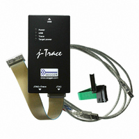
8.10.00 J-TRACE ARM
Manufacturer Part Number
8.10.00 J-TRACE ARM
Description
JTAG EMULATOR ARM7/ARM9 ETM
Manufacturer
Segger Microcontroller Systems
Type
Emulatorr
Specifications of 8.10.00 J-TRACE ARM
Contents
Emulation Module
For Use With/related Products
ARM7, ARM9
Lead Free Status / RoHS Status
Lead free / RoHS Compliant
Other names
899-1006


122
5.9
5.9.1
5.9.2
5.9.3
J-Link / J-Trace (UM08001)
The ARM7/9 architecture requires cooperation of the CPU to access memory when the
CPU is running (not in debug mode). This means that memory can not normally be
accessed while the CPU is executing the application program. The normal way to read
or write memory is to halt the CPU (put it into debug mode) before accessing mem-
ory. Even if the CPU is restarted after the memory access, the real time behavior is
significantly affected; halting and restarting the CPU costs typically multiple millisec-
onds. For this reason, most debuggers do not even allow memory access if the CPU is
running.
Fortunately, there is one other option: DCC (Direct communication channel) can be
used to communicate with the CPU while it is executing the application program. All
that is required is that the application program calls a DCC handler from time to
time. This DCC handler typically requires less than 1 µs per call.
The DCC handler, as well as the optional DCC abort handler, is part of the J-Link soft-
ware package and can be found in the Samples\DCC\IAR directory of the package.
•
•
•
An application program that uses DCC is JLink.exe.
The target DCC handler is a simple C-file taking care of the communication. The func-
tion DCC_Process() needs to be called regularly from the application program or
from an interrupt handler. If a RTOS is used, a good place to call the DCC handler is
from the timer tick interrupt. In general, the more often the DCC handler is called,
the faster memory can be accessed. On most devices, it is also possible to let the
DCC generate an interrupt which can be used to call the DCC handler.
An optional DCC abort handler (a simple assembly file) can be included in the appli-
cation. The DCC abort handler allows data aborts caused by memory reads/writes via
DCC to be handled gracefully. If the data abort has been caused by the DCC commu-
nication, it returns to the instruction right after the one causing the abort, allowing
the application program to continue to run. In addition to that, it allows the host to
detect if a data abort occurred.
In order to use the DCC abort handler, 3 things need to be done:
•
•
•
Using DCC for memory access
An application program on the host (typically a debugger) that uses DCC
A target application program that regularly calls the DCC handler
The supplied abort handler should be installed (optional)
Place a branch to DCC_Abort at address 0x10 ("vector" used for data aborts)
Initialize the Abort-mode stack pointer to an area of at least 8 bytes of stack
memory required by the handler
Add the DCC abort handler assembly file to the application
What is required?
Target DCC handler
Target DCC abort handler
CHAPTER 5
© 2004-2011 SEGGER Microcontroller GmbH & Co. KG
Working with J-Link and J-Trace
Related parts for 8.10.00 J-TRACE ARM
Image
Part Number
Description
Manufacturer
Datasheet
Request
R

Part Number:
Description:
CONNECTOR JTAG-ARM ISOLATION
Manufacturer:
Segger Microcontroller Systems
Datasheet:

Part Number:
Description:
ADAPTER ARM TARGET 14PIN RIBBON
Manufacturer:
Segger Microcontroller Systems
Datasheet:

Part Number:
Description:
JTAG EMULATOR FOR ARM CORES
Manufacturer:
Segger Microcontroller Systems
Datasheet:

Part Number:
Description:
JTAG EMULATOR FOR ARM CORES
Manufacturer:
Segger Microcontroller Systems
Datasheet:

Part Number:
Description:
PROGRAMMING TOOL FOR MCU
Manufacturer:
Segger Microcontroller Systems
Datasheet:

Part Number:
Description:
PROGRAMMING TOOL FOR ST7 MCU
Manufacturer:
Segger Microcontroller Systems
Datasheet:

Part Number:
Description:
PROGRAMMING TOOL FOR STM8
Manufacturer:
Segger Microcontroller Systems
Datasheet:

Part Number:
Description:
PROGRAMMER JTAG FOR ARM CORES
Manufacturer:
Segger Microcontroller Systems
Datasheet:

Part Number:
Description:
JTAG EMULATOR USB ETHERNET ARM
Manufacturer:
Segger Microcontroller Systems
Datasheet:

Part Number:
Description:
EMULATOR JTAG/SWD CORTEX M3
Manufacturer:
Segger Microcontroller Systems
Datasheet: